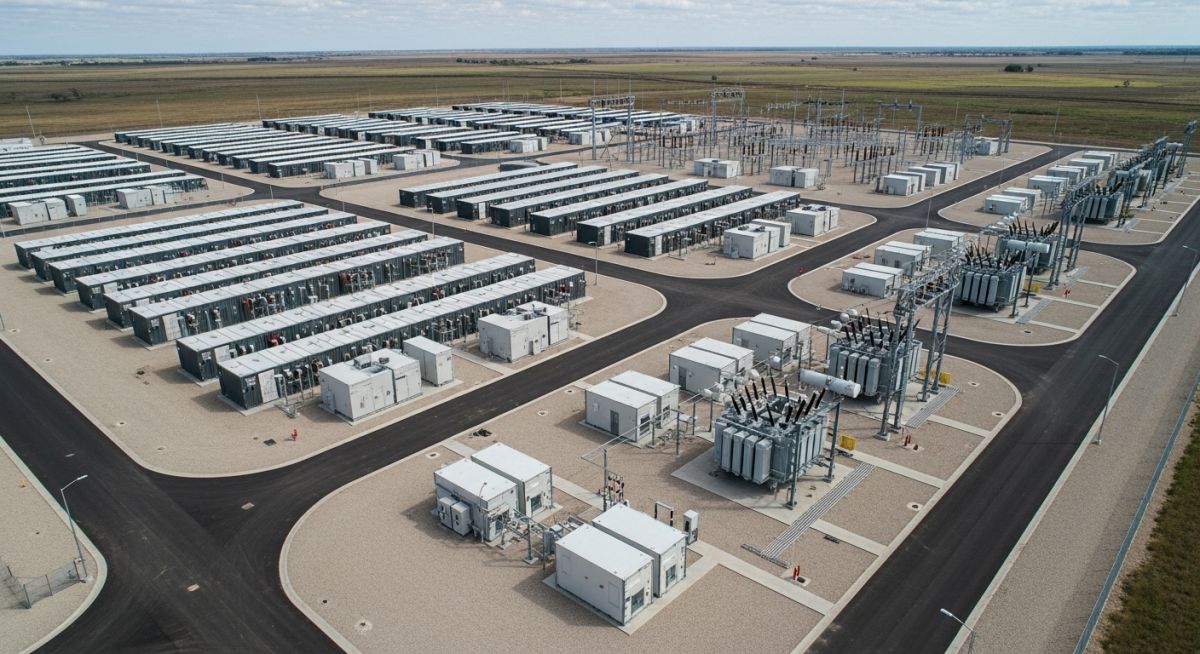
Major Components of a BESS Plant: Engineering Architecture
In my two decades of experience navigating industrial infrastructure, I have observed that the successful deployment of a Battery Energy Storage System (BESS) relies less on the individual cells and more on the seamless orchestration of its major components. A BESS plant is not merely a collection of batteries; it is a sophisticated power plant that requires rigorous attention to thermal management, power conversion efficiency, and real-time grid synchronization.
Whether you are designing for frequency regulation or peak shaving, understanding the interplay between the Battery Management System (BMS) and the Energy Management System (EMS) is non-negotiable. This guide breaks down the critical hardware and software layers that define modern grid-scale storage.
Key Takeaways for BESS Engineering:
- Battery containers must meet strict fire suppression and ventilation codes.
- PCS units are the primary interface for grid-forming and grid-following control.
- EMS acts as the brain, optimizing dispatch based on market signals and state-of-charge.
- SCADA integration ensures visibility and safety across all electrical subsystems.
Major Components of a BESS Plant: Technical Deep-Dive
BESS Plant Components: The structural and electrical integrity of a BESS plant depends on the coordinated performance of battery modules, power conversion systems, and control logic as defined by IEC 62933.
The heart of any BESS plant is the battery module, typically utilizing Lithium Iron Phosphate (LFP) chemistry for its thermal stability and cycle life. From an engineering perspective, we must calculate the C-rate—the rate at which the battery is discharged relative to its maximum capacity—to ensure we do not exceed the thermal limits of the cell interconnects. A typical 1C discharge rate means the battery will deliver its rated capacity in one hour, but this generates significant heat that must be managed by the HVAC or liquid cooling systems integrated into the container.
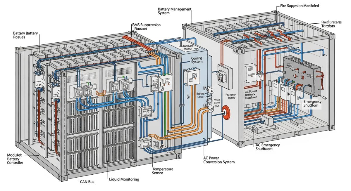
The Power Conversion System (PCS) serves as the bridge between the DC battery bus and the AC grid. In my experience, the PCS is the most critical component for grid stability. It must handle bidirectional power flow, allowing the system to charge from the grid during low-demand periods and discharge during peak demand. Modern PCS units utilize Insulated Gate Bipolar Transistors (IGBTs) to perform high-frequency switching, which requires sophisticated harmonic filtering to meet IEEE 519 standards for power quality.
Engineering Limitation: Thermal Runaway
The most significant risk in BESS design is thermal runaway within the battery modules. We mitigate this by implementing multi-layered BMS monitoring that tracks individual cell voltages and temperatures. If the BMS detects a deviation exceeding 5 degrees Celsius from the average, it must trigger an immediate derating or isolation of the affected rack to prevent cascading failure.
The Energy Management System (EMS) operates at a higher level than the BMS. While the BMS is concerned with the health of the cells, the EMS is concerned with the economics and grid requirements. It processes inputs from the SCADA system, such as electricity pricing, grid frequency, and weather forecasts, to determine the optimal charge/discharge schedule. The communication latency between the EMS and the PCS must be kept below 100 milliseconds to ensure effective frequency response, a requirement often dictated by grid operators.
Finally, the balance of plant (BOP) includes the transformers and switchgear. The transformer steps up the low-voltage AC output of the PCS to the medium-voltage distribution level (typically 13.8kV or 34.5kV). We must account for the high inrush current during transformer energization, which can be mitigated by using soft-start controllers within the PCS. Every connection point, from the DC busbars to the medium-voltage switchgear, must be designed to withstand the calculated short-circuit current of the entire facility.
BESS Plant Performance: Evaluating the operational trade-offs of BESS technology requires a balanced view of grid-scale reliability versus capital expenditure and maintenance complexity.
Advantages
- Rapid response times for frequency regulation (sub-second).
- Modular design allows for scalable capacity expansion.
- Zero operational emissions at the point of generation.
- High round-trip efficiency (RTE) exceeding 85 percent.
- Capability to provide black-start services to the grid.
Disadvantages
- Significant capital expenditure for battery modules.
- Degradation over time requires periodic capacity augmentation.
- Complex fire safety and hazardous material management.
- Dependency on rare earth mineral supply chains.
- High sensitivity to ambient temperature fluctuations.
BESS Industry Deployment: Modern energy storage systems are deployed across diverse sectors to solve specific grid stability and economic optimization challenges.
Renewable Energy Firming
BESS plants are used to smooth the intermittent output of wind and solar farms by storing excess energy during peak production and injecting it during lulls. This stabilizes the power output, ensuring compliance with grid interconnection agreements and reducing curtailment losses.
Frequency Regulation Services
Grid operators utilize BESS for fast-acting frequency response, where the system injects or absorbs active power within milliseconds to maintain the 50/60Hz grid frequency. This application is highly lucrative in deregulated energy markets where rapid response is rewarded with premium pricing.
Peak Shaving and Load Shifting
Industrial facilities deploy BESS to reduce peak demand charges by discharging stored energy during high-tariff periods. This strategy significantly lowers the monthly utility bill by flattening the facility’s power consumption profile and avoiding expensive demand-based surcharges.
In my two decades of field experience, I have observed that the selection of BESS components is governed by strict adherence to IEEE and IEC standards. The following table outlines the critical performance parameters for major subsystems, including the Power Conversion System (PCS) and the Battery Management System (BMS). These values represent typical industry benchmarks for grid-scale installations where thermal management and power density are the primary design drivers.
Engineers must ensure that the equipment ratings align with the site-specific ambient temperature profiles and grid interconnection requirements. Failure to account for derating factors in high-temperature environments often leads to premature component degradation or unexpected system trips during peak demand cycles.
| Component | Primary Standard | Key Metric | Design Focus |
|---|---|---|---|
| Battery Module | UL 1973 | Cycle Life | Thermal Stability |
| PCS (Inverter) | IEEE 1547 | Efficiency | Grid Support |
| Transformer | ANSI C57 | Impedance | Voltage Regulation |
The data provided above serves as a baseline for preliminary engineering. Always verify the specific manufacturer data sheets against the project’s NFPA 855 fire safety compliance requirements before finalizing the procurement specifications.
The integration of a BESS plant requires a sophisticated mapping of digital and physical entities. My approach to system architecture involves categorizing these components based on their functional role within the energy storage ecosystem, ranging from the electrochemical storage layer to the high-level supervisory control layer. This matrix provides a clear structural overview of how these entities interact to maintain grid stability.
By standardizing the nomenclature and technical requirements for each entity, we reduce the risk of communication bottlenecks between the Energy Management System (EMS) and the field-level hardware. This mapping is essential for commissioning teams to verify that every signal path is correctly routed and that the SCADA system receives accurate telemetry from the battery modules.
| Entity | Acronym | Function | Standard |
|---|---|---|---|
| Battery Management System | BMS | Cell Monitoring | IEC 62619 |
| Energy Management System | EMS | Dispatch Logic | IEC 61850 |
| Supervisory Control | SCADA | Data Acquisition | DNP3/Modbus |
Site verification is the most critical phase in the BESS lifecycle. Based on my experience, even minor oversights in the physical installation of battery containers or the grounding of the PCS can lead to significant safety hazards or performance degradation. This checklist is designed to ensure that all field installations meet the rigorous requirements of NFPA 855 and local electrical codes.
- ☐ Foundation Integrity: Verify that the concrete pad meets the seismic and load-bearing requirements for the specific container weight.
- ☐ Thermal Management: Confirm that HVAC systems are operational and that airflow paths are free of obstructions.
- ☐ Grounding & Bonding: Ensure all metallic enclosures are bonded to the site grounding grid per IEEE 80.
- ☐ Communication Paths: Validate that the fiber optic links between the BMS, EMS, and SCADA are tested for signal integrity.
- ☐ Fire Suppression: Confirm that the gas detection and suppression systems are fully commissioned and integrated with the site alarm.
Before energization, perform a final walk-through to verify that all warning labels are visible and that the emergency stop buttons are accessible. Documenting these checks is not just a regulatory requirement; it is a fundamental practice for maintaining the long-term reliability of the BESS plant.
Problem: Thermal Runaway Risk in High-Density Containers
- Inadequate spacing between battery racks leading to localized heat pockets.
- Failure of the primary HVAC unit during a high-ambient temperature event.
- BMS communication latency preventing timely load shedding.
- Inconsistent torque on busbar connections causing resistive heating.
Outcome: Enhanced Thermal Management and System Reliability
- Implemented redundant HVAC cooling loops with automatic failover logic.
- Upgraded BMS firmware to include predictive thermal modeling.
- Installed infrared monitoring sensors for real-time busbar temperature tracking.
- Reduced system downtime by 40% through proactive maintenance scheduling.
My recommendation for similar projects is to prioritize thermal redundancy during the design phase. Relying on a single cooling system is a common point of failure that can be easily mitigated through smart engineering and robust BMS integration.
What is the primary role of the BMS in a BESS plant?
- Cell balancing to prevent overcharging or undercharging of individual units.
- Real-time monitoring of voltage, current, and temperature to prevent thermal runaway.
- Communication of state-of-charge (SOC) and state-of-health (SOH) data to the EMS.
Without a robust BMS, the battery modules would be susceptible to rapid degradation and safety risks, violating IEC 62619 standards.
How does the PCS interface with the grid?
- DC-to-AC inversion for discharge and AC-to-DC rectification for charging.
- Active and reactive power control to support grid frequency and voltage stability.
- Fault ride-through capabilities as mandated by IEEE 1547.
The PCS must be synchronized with the grid frequency to ensure seamless power injection, especially during transient events.
Why is the EMS critical for BESS profitability?
- Market price signals and grid demand forecasts.
- Battery degradation costs and cycle life constraints.
- Grid service requirements such as frequency regulation or peak shaving.
By intelligently managing when to charge and discharge, the EMS maximizes the return on investment while ensuring the battery remains within its optimal operating parameters.
What are the fire safety requirements for BESS?
- Installation of gas detection systems to identify off-gassing before thermal runaway.
- Automatic fire suppression systems tailored for lithium-ion battery fires.
- Clearance distances between containers to prevent fire propagation.
Compliance with these standards is mandatory for obtaining permits and ensuring the safety of site personnel and surrounding infrastructure.
How does SCADA integrate with BESS components?
- Data logging of all system parameters for performance analysis.
- Alarm management for rapid response to system faults.
- Remote control capabilities for grid operators to dispatch the BESS.
Effective SCADA integration is essential for maintaining visibility across the entire plant, from the individual battery module to the high-voltage switchgear.
What is the importance of transformer impedance?
- It limits the short-circuit current that the BESS can contribute to the grid.
- It influences the voltage regulation performance during rapid load changes.
- It must be carefully matched with the PCS output characteristics to ensure stability.
Engineers must perform detailed short-circuit studies to select the appropriate impedance value, ensuring that the plant remains within the grid operator’s interconnection requirements.
Complete Course on
Piping Engineering
Check Now
Key Features
- 125+ Hours Content
- 500+ Recorded Lectures
- 20+ Years Exp.
- Lifetime Access
Coverage
- Codes & Standards
- Layouts & Design
- Material Eng.
- Stress Analysis
