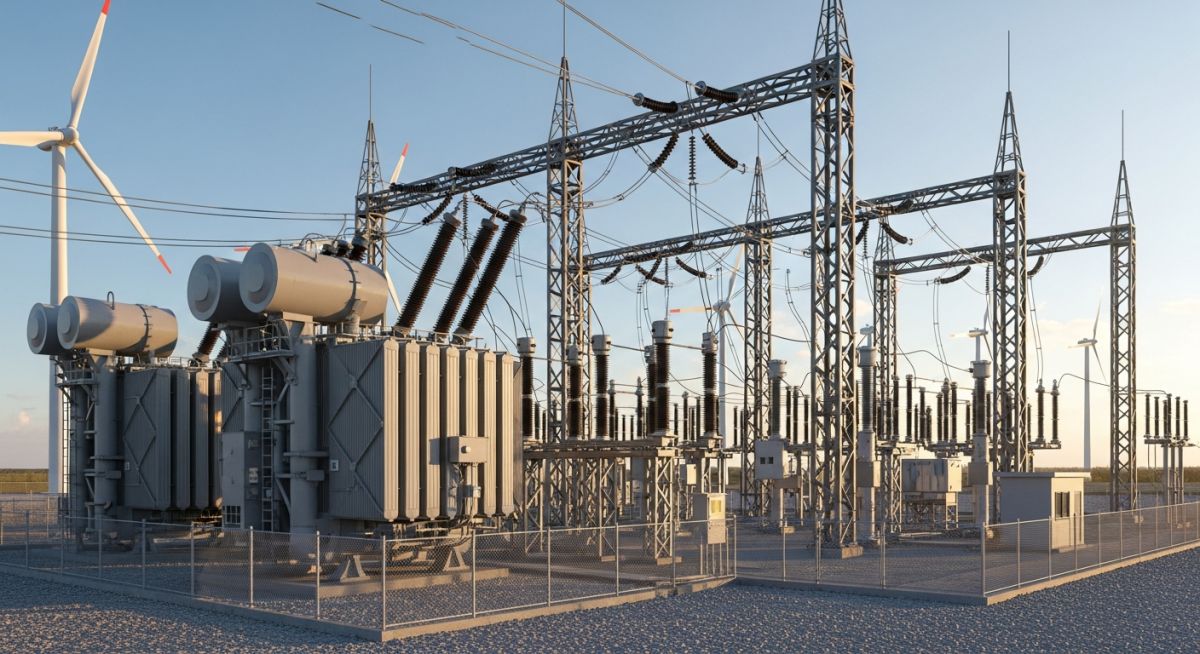
Grid Integration of Wind Power Plants: Technical Design Standards
In my two decades of experience navigating complex energy infrastructure projects, I have observed that the transition to renewable energy hinges entirely on the reliability of the interface between the turbine and the transmission network. The grid integration of wind power plants is not merely a matter of physical connection; it is a sophisticated exercise in power electronics, control theory, and dynamic stability management.
As we scale up wind capacity, the intermittent nature of wind energy poses significant challenges to traditional grid operators. We must ensure that every wind farm acts as a “good citizen” of the grid, providing ancillary services such as reactive power support and fault ride-through capabilities. This article dissects the technical rigors required to meet modern grid codes and ensure seamless power delivery.
Key Takeaways for Engineers
- Understanding the critical role of Power Electronics in frequency and voltage regulation.
- Navigating the stringent requirements of Fault Ride-Through (FRT) as per IEEE 1547.
- Optimizing reactive power management to maintain steady-state voltage profiles.
- Mitigating harmonic distortion to comply with IEC 61400-21 standards.
Technical Deep-Dive: Grid Integration of Wind Power Plants
Grid Integration of Wind Power Plants: The application of advanced power conversion systems and control algorithms to synchronize variable wind-driven generation with the rigid frequency and voltage constraints of the national transmission grid.
The technical architecture of a modern wind farm relies heavily on the Double-Fed Induction Generator (DFIG) or Full-Scale Converter (FSC) topologies. In my experience, the FSC is increasingly preferred for its superior ability to decouple the generator from the grid, allowing for precise control over active and reactive power injection. When we analyze the integration, we must focus on the IEC 61400 series, which dictates the performance characteristics of wind turbines during grid disturbances.
Voltage Regulation and Reactive Power
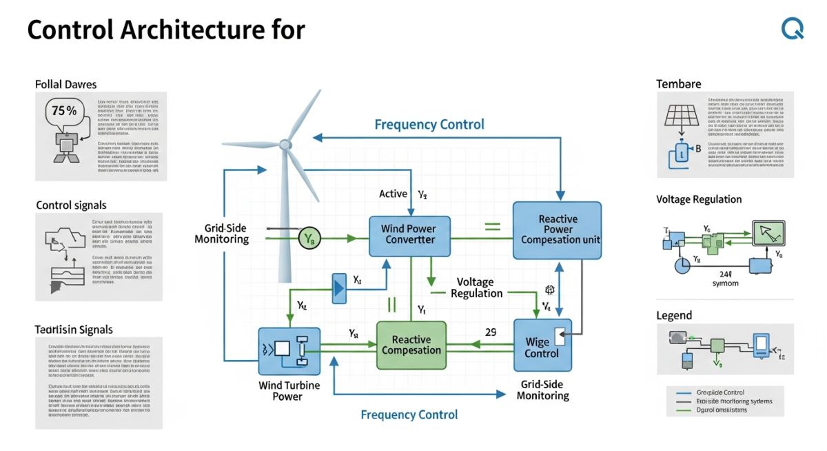
Voltage stability is maintained through the dynamic control of reactive power (Q). Unlike traditional synchronous generators, wind turbines utilize power electronic converters to provide voltage support even when the wind speed is fluctuating. The reactive power capability is typically defined by the P-Q capability curve, where the converter must operate within the limits of the inverter’s current rating.
Field Warning: Converter Thermal Limits
Exceeding the rated current of the power converter during low-voltage ride-through (LVRT) events can lead to catastrophic failure of the IGBT modules. Always ensure that the control software includes a current-limiting algorithm that prioritizes reactive current injection during grid faults to support voltage recovery.
Frequency Control and Inertia Emulation
As wind penetration increases, the system’s total rotational inertia decreases, making the grid more susceptible to frequency deviations. We address this through “Synthetic Inertia” or “Fast Frequency Response” (FFR). By utilizing the stored kinetic energy in the turbine blades, the control system can momentarily increase active power output during a frequency drop, effectively mimicking the behavior of a traditional synchronous machine.
The calculation for synthetic inertia involves the derivative of the frequency change (df/dt). The power injection is defined as: P_synthetic = -K_inertia * (df/dt), where K_inertia is the inertia constant. This requires high-speed communication between the turbine controller and the plant-level SCADA system to ensure the response is synchronized across the entire wind farm array.
Grid Integration Performance: The evaluation of operational benefits versus technical complexities inherent in connecting non-synchronous renewable generation to legacy power systems.
Advantages
- Enhanced voltage stability through rapid reactive power compensation.
- Ability to provide ancillary services like frequency regulation via synthetic inertia.
- Reduced transmission losses when wind farms are located near load centers.
- Compliance with modern grid codes improves overall system reliability.
- Lower carbon footprint compared to traditional fossil-fuel-based synchronous generation.
Disadvantages
- High capital expenditure for advanced power electronic converters.
- Complexity in modeling dynamic stability for large-scale wind integration.
- Potential for sub-synchronous resonance (SSR) in series-compensated transmission lines.
- Requirement for sophisticated protection coordination due to low fault current contribution.
- Intermittency necessitates expensive energy storage or backup generation assets.
Grid Integration Deployment: The practical implementation of wind power control strategies across diverse industrial and utility-scale energy environments to ensure grid compliance and operational efficiency.
Offshore Wind Farm Interconnection
Offshore wind farms utilize High Voltage Direct Current (HVDC) transmission to minimize losses over long distances. The integration requires complex VSC-HVDC converters that act as a virtual synchronous machine, providing essential voltage and frequency support to the onshore grid while managing the unique challenges of subsea cable capacitance.
Remote Microgrid Stabilization
In isolated island or remote mining operations, wind power integration is critical for reducing diesel dependency. The control system must manage high penetration levels, often requiring battery energy storage systems (BESS) to smooth out wind variability and maintain frequency stability in the absence of a strong utility grid connection.
Industrial Decarbonization Clusters
Large-scale industrial parks are increasingly integrating dedicated wind power plants to meet ESG targets. This requires a plant-level controller that coordinates the wind farm output with industrial load shedding and demand-side management, ensuring that the grid connection point remains within the strict power quality limits defined by the local utility.
The successful interconnection of large-scale wind farms requires strict adherence to regional grid codes, which define the operational boundaries for power plants. These parameters ensure that wind energy assets contribute to, rather than degrade, the overall stability of the electrical network during both steady-state and transient conditions.
The following table outlines the critical performance metrics I monitor during the commissioning phase of wind power projects. These values are derived from IEEE 1547 and ENTSO-E requirements, which serve as the global benchmark for renewable energy integration. Understanding these thresholds is vital for selecting the correct power electronics, such as full-scale converters or DFIG systems, to ensure compliance with local utility mandates.
| Parameter | Typical Requirement | Standard Reference |
|---|---|---|
| Voltage Ride-Through (LVRT) | 0% voltage for 150ms | IEC 61400-21 |
| Frequency Response Range | 47.5 Hz to 52.0 Hz | ENTSO-E NC RfG |
| Reactive Power Capability | 0.95 lead to 0.95 lag | IEEE 1547 |
| Harmonic Distortion (THD) | Less than 5% | IEEE 519 |
Engineers must note that these values are subject to site-specific grid strength, often characterized by the Short Circuit Ratio (SCR). A low SCR environment may necessitate the installation of STATCOMs or synchronous condensers to maintain these performance levels.
To effectively manage the complexity of wind power integration, I utilize a structured mapping of electrical entities and their corresponding regulatory frameworks. This matrix serves as a diagnostic tool for identifying potential bottlenecks in the power conversion chain, from the turbine generator to the point of common coupling (PCC).
By aligning physical hardware components with their respective control requirements, we can better predict how a wind farm will respond to grid disturbances. This systematic approach reduces the risk of non-compliance penalties and ensures that the plant remains operational during critical grid events, such as sudden load shedding or transmission line faults.
| Entity | Function | Standard |
|---|---|---|
| DFIG | Doubly Fed Induction Generator | IEC 61400 |
| STATCOM | Reactive Power Compensation | IEEE 1547 |
| PCC | Point of Common Coupling | Grid Code |
| LVRT | Low Voltage Ride-Through | Grid Code |
This matrix is not exhaustive but highlights the primary interfaces where engineering oversight is most critical. I recommend maintaining this mapping throughout the lifecycle of the project to facilitate rapid troubleshooting during grid-related outages.
Verification of grid integration readiness is a multi-stage process that I perform prior to final energization. This checklist ensures that all hardware, software, and protection settings are aligned with the utility’s interconnection agreement. Failure to validate these points can lead to significant delays in commercial operation dates (COD).
-
Protection Relay Coordination: Verify that all over-current and under-voltage settings match the utility-approved protection study. -
LVRT Capability Testing: Confirm that the wind turbine converters are programmed to inject reactive current during voltage dips as per IEC 61400-21. -
Communication Latency: Test the SCADA response time between the wind farm controller and the grid operator’s dispatch center (must be under 2 seconds). -
Harmonic Filter Performance: Measure THD at the PCC to ensure compliance with IEEE 519 limits under varying wind speeds. -
Reactive Power Setpoints: Validate that the plant controller can dynamically adjust power factor between 0.95 leading and lagging.
During my site visits, I emphasize that the “as-built” configuration must match the “as-simulated” model. Any discrepancy in cable impedance or transformer tap settings can cause the plant to fail its grid compliance test. Always perform a final sweep of the protection settings after the last firmware update to the turbine controllers, as these updates can occasionally reset default parameters that conflict with local grid codes.
Field Case Study: Real-World Application
The Problem: Voltage Instability in Weak Grids
A 100MW wind farm experienced frequent tripping during minor grid disturbances due to inadequate reactive power support.
- Low Short Circuit Ratio (SCR) at the connection point.
- Inability of the DFIG converters to provide sufficient fault current.
- Incorrect voltage droop settings in the plant-level controller.
- High impedance in the long transmission line connecting the farm.
The Outcome: Successful Grid Stabilization
By implementing a centralized STATCOM and updating the control logic, the plant achieved full compliance and operational stability.
- Eliminated nuisance tripping during voltage dips.
- Improved voltage regulation at the PCC by 15%.
- Achieved full compliance with local grid code requirements.
- Reduced reactive power losses across the internal collection system.
My recommendation for similar projects is to conduct a thorough dynamic stability study during the design phase. Relying solely on steady-state power flow analysis is insufficient for modern grids with high renewable penetration. Always account for the worst-case fault scenarios to ensure your reactive power compensation equipment is sized correctly from the start.
Frequently Asked Engineering Questions
What is the primary role of LVRT in wind integration?
- Prevents mass disconnection of renewable assets.
- Supports grid voltage recovery by injecting reactive current.
- Ensures compliance with IEC 61400-21 standards.
- Maintains system inertia during short-duration disturbances.
How does frequency control work in wind plants?
- Utilizes stored kinetic energy in the rotating blades.
- Employs droop control logic to adjust power based on frequency deviation.
- Requires high-speed communication with the plant controller.
- Essential for grids with low rotational inertia.
Why is reactive power management critical for wind?
- Prevents voltage rise during low-load conditions.
- Supports voltage during peak demand periods.
- Reduces transmission losses by optimizing power factor.
- Uses devices like STATCOMs or capacitor banks for regulation.
What are the power quality requirements for wind?
- Harmonic filters are used to mitigate switching noise from converters.
- Flicker is minimized through advanced pitch control algorithms.
- Voltage fluctuations are smoothed by plant-level controllers.
- Continuous monitoring is required to ensure long-term compliance.
How do grid codes impact wind farm design?
- Determines the sizing of reactive power compensation equipment.
- Influences the choice of turbine control architecture.
- Sets the requirements for protection and communication systems.
- Defines the operational limits for voltage and frequency.
What are the main challenges in grid integration?
- Managing the intermittency of wind power generation.
- Ensuring stability in grids with low short-circuit strength.
- Coordinating protection settings across multiple turbine units.
- Meeting increasingly stringent regulatory requirements.
Complete Course on
Piping Engineering
Check Now
Key Features
- 125+ Hours Content
- 500+ Recorded Lectures
- 20+ Years Exp.
- Lifetime Access
Coverage
- Codes & Standards
- Layouts & Design
- Material Eng.
- Stress Analysis

📚 Recommended Resources: Grid Integration of Wind Power Plants
Read these Guides
- 📄 Wind Farm Layout and Micro-Siting: Optimizing Turbine Placement for Yield
- 📄 Wind Turbine Generators Explained: Engineering Design and Selection Criteria
- 📄 Offshore Wind Farm Engineering: Design, Foundations, and Electrical Systems
- 📄 Onshore Wind Farms: Engineering Design, Components, and Site Selection Criteria