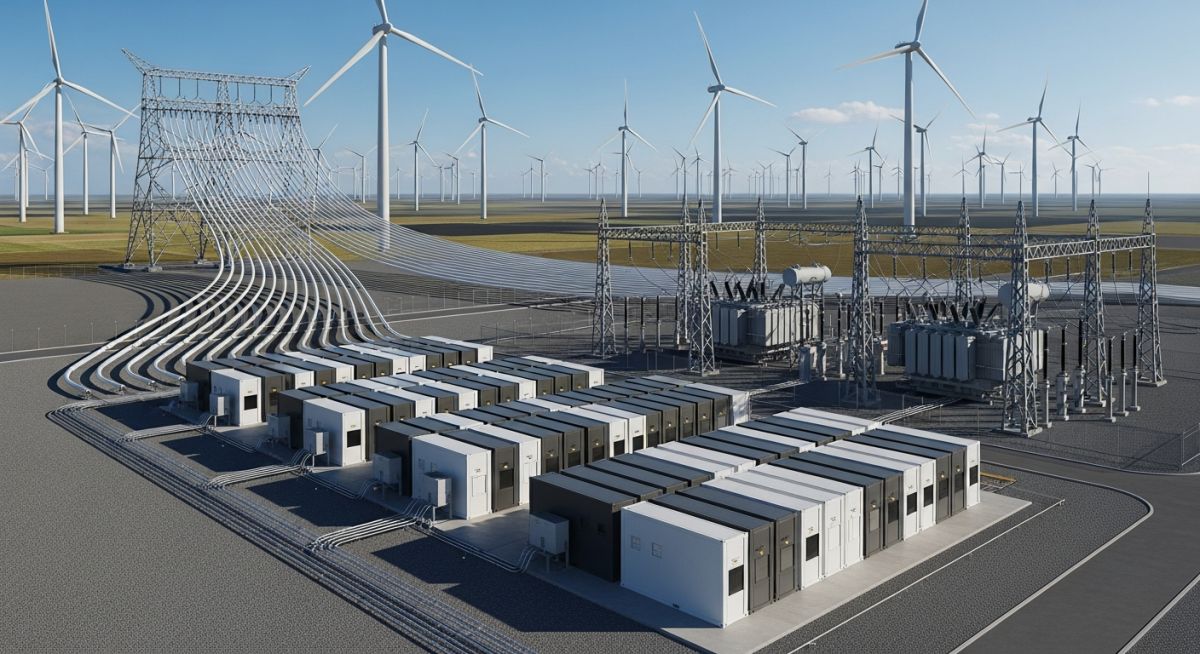
BESS Integration with Wind Power: Solving Intermittency Challenges
In my two decades of experience within the energy sector, I have observed that the primary hurdle for wind energy is not the generation capacity, but the inherent intermittency of the resource. Integrating a Battery Energy Storage System (BESS) into a wind power plant is no longer an optional upgrade; it is a fundamental requirement for modern grid stability.
This guide explores how we bridge the gap between volatile wind gusts and steady-state grid requirements. By utilizing advanced power electronics and control algorithms, we can transform a variable wind source into a dispatchable asset, effectively managing frequency response and energy arbitrage.
Key Takeaways
- BESS provides essential synthetic inertia to wind-heavy grids.
- AC-coupled vs. DC-coupled architectures dictate system efficiency.
- Energy arbitrage improves project IRR by shifting generation to peak hours.
- Compliance with grid codes is mandatory for all hybrid installations.
Technical Design for BESS Integration with Wind Power
BESS Integration with Wind Power: The engineering process of coupling electrochemical storage with wind turbine generators to provide active power control, ramp-rate limiting, and frequency regulation, adhering to ASME and IEC standards for electrical infrastructure.
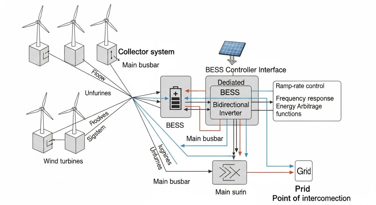
When designing a hybrid wind-BESS facility, we must first address the power conversion topology. In my experience, the choice between AC-coupled and DC-coupled systems is the most critical decision. AC-coupling allows for independent operation of the wind farm and the BESS, which simplifies the integration of storage into existing brownfield sites. However, DC-coupling, where the battery connects directly to the turbine’s DC bus, reduces conversion losses by eliminating redundant inverter stages.
Power Smoothing and Ramp-Rate Control
Wind power output can fluctuate significantly within seconds. To meet grid operator requirements, we implement ramp-rate limiting. The BESS acts as a high-speed buffer, absorbing excess energy during gusts and injecting power during lulls. The control logic is governed by the following relationship:
P_grid = P_wind + P_bess
Where P_grid is the target output, P_wind is the instantaneous wind generation, and P_bess is the battery power. We calculate the required BESS capacity based on the maximum expected ramp rate (MW/min) and the duration of the required smoothing window. If the wind farm has a rated capacity of 100 MW, and the grid code mandates a ramp rate of 10% per minute, the BESS must be sized to handle 10 MW of instantaneous power variation.
Field Warning: Thermal Management
Battery degradation is accelerated by high-frequency cycling. In my field assessments, I have seen premature failure of BESS modules due to inadequate HVAC systems in high-ambient-temperature wind farm locations. Always ensure the BESS container design accounts for the peak thermal load during simultaneous charging and discharging cycles.
Frequency Support and Synthetic Inertia
As traditional synchronous generators are retired, wind farms must provide synthetic inertia. By utilizing the BESS inverter’s fast-acting control, we can emulate the inertial response of a rotating mass. This is achieved through a frequency-watt droop control loop, where the BESS output is adjusted based on the deviation of the grid frequency from the nominal 50Hz or 60Hz.
The response time for this service must be in the millisecond range to be effective. We utilize IEEE 1547 compliant inverters that support fast frequency response (FFR) capabilities. This ensures that the wind-BESS hybrid can participate in ancillary service markets, providing a secondary revenue stream that significantly enhances the project’s economic viability.
Hybrid System Performance: The technical trade-offs between operational flexibility and capital expenditure in BESS-integrated wind power plants, evaluated against long-term asset lifecycle costs.
Advantages
- Enhanced grid compliance via active power smoothing.
- Revenue generation through energy arbitrage and ancillary services.
- Reduction in wind curtailment during periods of low demand.
- Provision of synthetic inertia for grid frequency stability.
- Improved project IRR through optimized dispatch strategies.
Disadvantages
- High initial capital expenditure for battery modules.
- Complex control integration with existing turbine SCADA.
- Accelerated battery degradation due to high-frequency cycling.
- Increased maintenance requirements for power electronics.
- Regulatory uncertainty regarding hybrid asset classification.
Renewable Energy Deployment: The practical implementation of BESS in diverse industrial and utility-scale wind environments to solve specific grid-interconnection and economic challenges.
Utility-Scale Grid Balancing
Large-scale wind farms utilize BESS to provide primary frequency response to the national grid. By maintaining a state-of-charge buffer, the system can inject or absorb power within milliseconds to stabilize frequency deviations, effectively replacing the role of traditional spinning reserves.
Remote Microgrid Stabilization
In isolated island or remote mining operations, wind power is often the primary energy source. BESS integration is vital here to manage the high volatility of wind, ensuring that the microgrid remains stable even when wind speeds drop suddenly, preventing blackouts and reducing reliance on diesel backup generators.
Energy Arbitrage for Merchant Wind
Merchant wind farms without long-term power purchase agreements use BESS to store energy during low-price, high-wind periods. This energy is then discharged during peak demand hours when electricity prices are highest, maximizing the revenue per megawatt-hour generated by the wind turbines.
Integrating Battery Energy Storage Systems (BESS) into wind power plants requires a rigorous evaluation of performance metrics to ensure grid compliance and operational efficiency. In my experience, the selection of battery chemistry and power conversion system (PCS) architecture dictates the plant’s ability to handle rapid ramp-rate fluctuations inherent in wind generation. Engineers must prioritize round-trip efficiency (RTE) and cycle life when selecting lithium-ion or flow battery technologies for these high-duty applications.
The following table outlines the critical technical parameters that define the operational envelope for BESS units coupled with wind farms. These values are derived from IEEE 1547 standards for distributed energy resources and represent the baseline requirements for frequency regulation and power smoothing applications in modern utility-scale projects.
| Parameter | Typical Range | Standard Reference |
|---|---|---|
| Response Time | Less than 100 milliseconds | NERC BAL-001 |
| Cycle Life | 4,000 to 10,000 cycles | IEC 62619 |
| Round Trip Efficiency | 85% to 95% | IEEE 2030.2 |
| Depth of Discharge | 80% to 100% | UL 9540 |
By maintaining these parameters, operators can effectively mitigate the volatility of wind power, ensuring that the injected energy meets the strict quality standards demanded by transmission system operators (TSOs). Proper monitoring of these metrics is the foundation of a reliable BESS integration strategy.
The complexity of BESS integration with wind power plants necessitates a structured approach to mapping technical entities against their respective functional roles. In my professional practice, I utilize this matrix to align hardware specifications with grid-side requirements, ensuring that every component—from the battery management system (BMS) to the power conversion system (PCS)—contributes to the overall stability of the wind-storage hybrid system.
This matrix serves as a cross-reference tool for engineers to identify the intersection between physical hardware, control software, and regulatory compliance. By standardizing these relationships, we reduce the risk of integration failures and optimize the lifecycle cost of the storage asset.
| Entity | Primary Function | Standard |
|---|---|---|
| BMS | Cell balancing and thermal safety | IEC 62619 |
| PCS | DC to AC power conversion | IEEE 1547 |
| EMS | Grid dispatch and optimization | IEC 61850 |
Effective management of these entities requires a deep understanding of how they interact under transient wind conditions. The integration of these systems is not merely a hardware challenge but a sophisticated software orchestration task that defines the modern renewable energy landscape.
BESS Integration Site Verification: Successful deployment of BESS at a wind site requires a systematic verification process to ensure all electrical, thermal, and control systems are fully operational and compliant with grid codes. This checklist provides a structured approach for site engineers to validate the installation before commissioning.
-
Communication Latency: Verify that the round-trip communication latency between the wind turbine controller and the BESS EMS is below 20ms to ensure effective frequency response. -
Thermal Management: Confirm that HVAC and liquid cooling systems are calibrated to maintain battery cell temperatures within the manufacturer’s optimal range, as per UL 9540. -
Protection Coordination: Validate that the BESS protection relays are coordinated with the wind farm’s main substation breakers to prevent nuisance tripping during fault ride-through events. -
Grid Code Compliance: Perform a site acceptance test (SAT) to confirm the BESS can provide synthetic inertia and primary frequency response as required by local grid operators. -
Safety Interlocks: Ensure all emergency stop circuits and fire suppression systems are fully integrated and tested for manual and automated activation.
Following this checklist ensures that the BESS integration is not only technically sound but also safe for long-term operation. In my experience, skipping these verification steps often leads to premature component failure or grid non-compliance penalties that can significantly impact the project’s internal rate of return.
The Challenge: High Wind Curtailment and Frequency Instability
A 200MW wind farm in a remote region faced severe grid constraints, leading to frequent curtailment and unstable frequency regulation during high-wind periods.
- Excessive wind generation exceeding local transmission capacity.
- Inability to provide fast frequency response (FFR) to the grid.
- High revenue loss due to mandatory curtailment orders.
- Voltage fluctuations caused by rapid wind speed changes.
The Outcome: Successful BESS Integration and Revenue Optimization
The installation of a 50MW/100MWh BESS enabled the plant to capture curtailed energy and provide critical grid services, transforming the site’s economic profile.
- Reduced curtailment by 65% through energy shifting.
- Achieved full compliance with regional FFR requirements.
- Increased annual revenue by 18% via ancillary service markets.
- Stabilized local voltage profiles during transient wind events.
My recommendation for similar projects is to conduct a thorough site-specific load flow analysis before sizing the BESS. The economic viability of these systems is highly dependent on the local market structure for ancillary services and the specific curtailment patterns of the wind resource.
How does BESS improve wind power ramp rates?
- Smoothing of power output during sudden wind gusts.
- Reduction of mechanical stress on turbine components.
- Compliance with grid connection agreements regarding power gradients.
What is the role of BESS in frequency support?
- Immediate response to frequency drops (under-frequency events).
- Active power modulation to support grid frequency recovery.
- Enhanced grid resilience through decentralized control architectures.
How does energy arbitrage work with wind-BESS?
- Charging during off-peak hours or high-wind curtailment events.
- Discharging during peak demand to capture price spreads.
- Optimization through predictive analytics and market forecasting.
What are the primary safety standards for BESS?
- UL 9540 for energy storage system safety.
- IEC 62619 for lithium-ion battery safety requirements.
- NFPA 855 for the installation of stationary energy storage systems.
How is BESS sizing determined for wind farms?
- Analysis of historical wind speed data and power output.
- Evaluation of grid service requirements and market pricing.
- Trade-off analysis between capital expenditure and operational revenue.
What is the expected lifespan of a BESS?
- Impact of cycle depth on battery degradation.
- Importance of regular maintenance and firmware updates.
- End-of-life considerations and battery recycling programs.
Complete Course on
Piping Engineering
Check Now
Key Features
- 125+ Hours Content
- 500+ Recorded Lectures
- 20+ Years Exp.
- Lifetime Access
Coverage
- Codes & Standards
- Layouts & Design
- Material Eng.
- Stress Analysis

📚 Recommended Resources: BESS Integration with Wind Power
Read these Guides
- 📄 BESS Integration with Solar Power Plants: Design and Operational Strategies
- 📄 BESS Sizing Calculations: Optimizing Battery Energy Storage System Capacity
- 📄 Engineering Utility-Scale BESS Plant Design: A Comprehensive Technical Guide
- 📄 Power Conversion System Design: Essential Guide for Modern Grid Integration