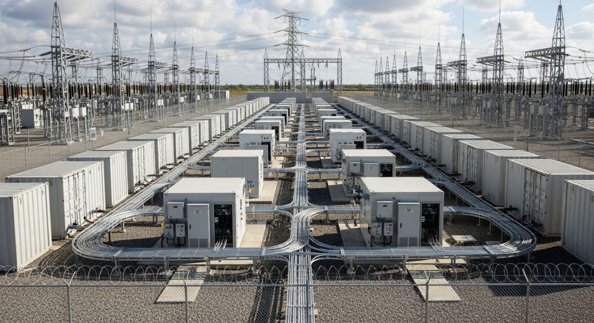
Designing a Utility-Scale BESS Plant: Engineering and Development
In my two decades of experience managing complex energy infrastructure, I have found that a Utility-Scale BESS Plant is far more than just a collection of batteries. It is a high-stakes balancing act between electrochemical performance, thermal stability, and grid-code compliance. As we shift toward intermittent renewable sources, the ability to deploy reliable storage is the single most critical factor in grid resilience.
This guide breaks down the technical requirements for successful project development. We will navigate the complexities of battery chemistry selection, the nuances of thermal management, and the rigorous demands of grid interconnection. Whether you are an EPC lead or a systems engineer, understanding these foundational elements is essential for delivering a project that is both bankable and safe.
Key Takeaways for EPC Success:
- Prioritize thermal management early in the site layout phase to prevent cascading failures.
- Ensure strict adherence to NFPA 855 for fire protection and suppression.
- Validate grid interconnection requirements against local utility standards before finalizing PCS specifications.
- Optimize the DC-to-AC ratio to maximize round-trip efficiency and project IRR.
Technical Architecture of a Utility-Scale BESS Plant
Utility-Scale BESS Plant Architecture: The integrated design of battery modules, power conversion systems, and balance-of-plant infrastructure required to meet specific grid-frequency response and energy-shifting performance metrics.
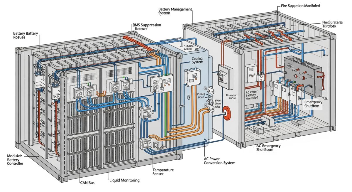
Designing a robust system begins with the selection of the battery chemistry. Lithium Iron Phosphate (LFP) has become the industry standard for utility-scale applications due to its superior thermal stability and cycle life compared to Nickel Manganese Cobalt (NMC). When calculating the total energy capacity, we must account for the Depth of Discharge (DoD) and the degradation curve over the project’s 20-year lifespan.
The Power Conversion System (PCS) acts as the bridge between the DC battery racks and the AC grid. In my experience, the selection of the inverter topology—centralized versus string—significantly impacts the plant’s availability. A centralized inverter offers higher efficiency and lower capital costs, but a string-based architecture provides superior granularity, allowing the system to continue operating even if one string experiences a fault.
Engineering Warning: Thermal Runaway Mitigation
Thermal management is the most critical safety parameter. If the cooling system fails, the battery cells can enter a state of thermal runaway. You must design redundant HVAC or liquid cooling loops and ensure that the fire suppression system is rated for the specific chemistry of the battery modules. Always refer to UL 9540 for safety certification requirements.
Grid interconnection requires a deep understanding of the FERC and NERC standards. The BESS must be capable of providing ancillary services such as frequency regulation, voltage support, and black-start capability. The calculation for the transformer sizing must consider the peak power output of the PCS, including the potential for short-term overloads during grid disturbances.
Finally, the layout must account for the physical spacing between containers to prevent fire propagation. Following the NFPA 855 guidelines, we typically maintain a minimum separation distance of 3 to 10 feet, depending on the fire-rating of the container walls and the presence of automated suppression systems.
Utility-Scale BESS Performance Trade-offs: The technical and economic evaluation of deploying large-scale battery storage systems versus traditional peaking generation assets.
Advantages
- Rapid response times for frequency regulation (sub-second).
- Zero operational emissions during energy discharge cycles.
- Modular scalability allows for phased project expansion.
- High round-trip efficiency (RTE) exceeding 85 percent.
- Reduced reliance on fossil-fuel-based peaking plants.
Disadvantages
- Significant capital expenditure for battery modules.
- Complex fire safety and thermal management requirements.
- Degradation over time necessitates capacity augmentation.
- Supply chain volatility for critical minerals like lithium.
- Stringent grid interconnection and permitting timelines.
Utility-Scale BESS Deployment Scenarios: The strategic application of energy storage systems to solve specific grid stability and economic optimization challenges in modern power markets.
Grid Frequency Regulation
BESS plants provide instantaneous power injection or absorption to maintain grid frequency within narrow operational bands. This application requires high-power, short-duration discharge cycles that leverage the rapid response capabilities of modern power electronics.
Renewable Energy Time-Shifting
By storing excess solar or wind energy during peak production hours, BESS systems allow for the dispatch of clean energy during periods of high demand. This effectively flattens the duck curve and increases the utilization rate of existing renewable assets.
Transmission Congestion Relief
Strategically located BESS installations can defer the need for expensive transmission line upgrades by injecting power locally during peak load events. This provides a cost-effective alternative to traditional infrastructure reinforcement in constrained grid segments.
When evaluating a Utility-Scale BESS Plant, engineers must reconcile the inherent trade-offs between energy density, cycle life, and thermal stability. The following table outlines the critical performance metrics that dictate the selection of battery chemistry and the subsequent design of the balance-of-plant (BOP) infrastructure. These values represent industry-standard benchmarks for lithium-ion technologies, specifically focusing on Nickel Manganese Cobalt (NMC) and Lithium Iron Phosphate (LFP) chemistries, which currently dominate the utility-scale market.
It is imperative to note that these parameters are subject to degradation over time, influenced heavily by the depth of discharge (DoD) and the ambient operating temperature of the containerized units. Designers must apply appropriate derating factors based on the IEEE 1679 standard to ensure the system meets its nameplate capacity throughout the project’s operational life. Failure to account for these variables during the initial sizing phase often leads to premature capacity loss and increased operational expenditure (OPEX) due to frequent cell balancing or module replacement requirements.
The successful deployment of a Utility-Scale BESS Plant requires a rigorous mapping of electrical, mechanical, and safety entities. This matrix serves as a foundational guide for EPC project managers to ensure that all subsystems—from the Battery Management System (BMS) to the Power Conversion System (PCS)—are interoperable and compliant with international grid codes. By standardizing these entities, we reduce the risk of integration failures during the commissioning phase.
Each entity listed below is governed by specific regulatory frameworks that dictate the design, testing, and installation procedures. For instance, the PCS must adhere to IEEE 1547 for grid interconnection, while the fire suppression systems must be validated against the latest NFPA 855 requirements. Maintaining this matrix throughout the project lifecycle ensures that any design changes are cross-referenced against these critical standards, preventing non-compliance issues that could delay the commercial operation date (COD).
| Entity | Primary Function | Standard |
|---|---|---|
| BMS | Cell balancing and state-of-charge monitoring | IEC 62619 |
| PCS | DC to AC power conversion | IEEE 1547 |
| HVAC | Thermal management and humidity control | ASHRAE 90.1 |
Before finalizing the EPC design for a Utility-Scale BESS Plant, I always insist on a comprehensive site verification process. This checklist is designed to mitigate risks associated with soil stability, grid access, and environmental compliance. Each item must be signed off by the lead engineer to ensure that the physical site conditions align with the theoretical design parameters established during the front-end engineering design (FEED) phase.
- ☐Geotechnical Assessment: Verify soil bearing capacity meets the requirements for heavy containerized battery units and concrete pad foundations.
- ☐Grid Interconnection Point: Confirm the physical distance to the substation and the availability of existing switchgear capacity per IEEE 1547.
- ☐Thermal Management Access: Ensure adequate clearance for HVAC maintenance and airflow paths to prevent localized hot spots within the battery enclosures.
- ☐Fire Suppression Infrastructure: Validate the availability of water supply or clean agent storage for fire protection systems as mandated by NFPA 855.
- ☐Environmental Compliance: Check local noise ordinances and flood zone mapping to ensure the site layout complies with regional zoning laws.
Following this checklist is not merely a procedural formality; it is a critical engineering safeguard. In my experience, the most common failures in BESS projects stem from neglecting the interaction between the battery system and the local environment. By verifying these parameters early, we ensure that the structural and electrical designs are robust enough to handle the operational stresses of a 20-year project lifespan.
Problem: Thermal Instability in High-Ambient Environments
A 50MW BESS project experienced significant capacity degradation during the first summer of operation due to inadequate thermal management.
- Insufficient HVAC cooling capacity for peak summer temperatures.
- Poor airflow distribution within the containerized battery racks.
- Lack of real-time thermal monitoring at the module level.
- Inaccurate derating calculations during the initial design phase.
Outcome: Optimized Thermal Control and System Recovery
The project team successfully restored system performance through a targeted retrofit and control logic update.
- Upgraded HVAC units with higher cooling capacity and redundant fans.
- Implemented advanced BMS algorithms for active thermal balancing.
- Reduced annual capacity degradation by 15% through improved cooling.
- Achieved full compliance with NFPA 855 safety standards.
My recommendation for future projects is to prioritize thermal modeling during the FEED stage. Never assume that standard container cooling is sufficient for extreme climates; always perform a site-specific heat load calculation that accounts for the maximum possible ambient temperature and the internal heat generation of the battery cells during high-rate charging cycles.
Frequently Asked Engineering Questions
How does battery chemistry influence EPC design?
- LFP chemistries generally require less aggressive cooling but occupy more physical space due to lower energy density.
- NMC chemistries offer higher density but demand more sophisticated thermal monitoring and fire suppression systems per NFPA 855.
- EPC engineers must adjust container layouts and HVAC sizing based on the specific heat release rates of the chosen chemistry.
What are the primary grid interconnection challenges?
- Compliance with IEEE 1547 is mandatory for all inverter-based resources to ensure grid stability.
- Engineers must conduct detailed power flow and short-circuit studies to determine the impact on existing substation infrastructure.
- The coordination between the BESS controller and the utility’s SCADA system is critical for frequency regulation and voltage support services.
How is thermal management optimized for BESS?
- Liquid cooling systems are increasingly preferred for high-density utility-scale applications due to their superior heat transfer efficiency.
- Designers must ensure that the HVAC system is sized for the worst-case ambient temperature and maximum discharge power.
- Redundancy in cooling components is essential to prevent system-wide shutdowns during a single-point failure of an HVAC unit.
What role does the BMS play in safety?
- It continuously monitors cell voltage, current, and temperature to prevent overcharging or deep discharging.
- The BMS must be integrated with the site-level fire protection system to trigger emergency shutdowns if thermal runaway is detected.
- Adherence to IEC 62619 ensures that the BMS provides reliable protection under various fault conditions.
How do we ensure fire protection compliance?
- Systems must include gas detection, smoke detection, and automated suppression agents tailored to the battery chemistry.
- Physical separation distances between containers are required to prevent fire propagation between units.
- Regular testing and maintenance of fire suppression systems are mandatory to ensure they remain operational throughout the project life.
What are the key EPC project risks?
- Long lead times for critical components like inverters and battery modules can delay the commercial operation date.
- Integration failures between different vendors’ equipment often lead to significant commissioning delays.
- Evolving grid codes and safety standards require constant vigilance to ensure the design remains compliant until the final handover.
Complete Course on
Piping Engineering
Check Now
Key Features
- 125+ Hours Content
- 500+ Recorded Lectures
- 20+ Years Exp.
- Lifetime Access
Coverage
- Codes & Standards
- Layouts & Design
- Material Eng.
- Stress Analysis
