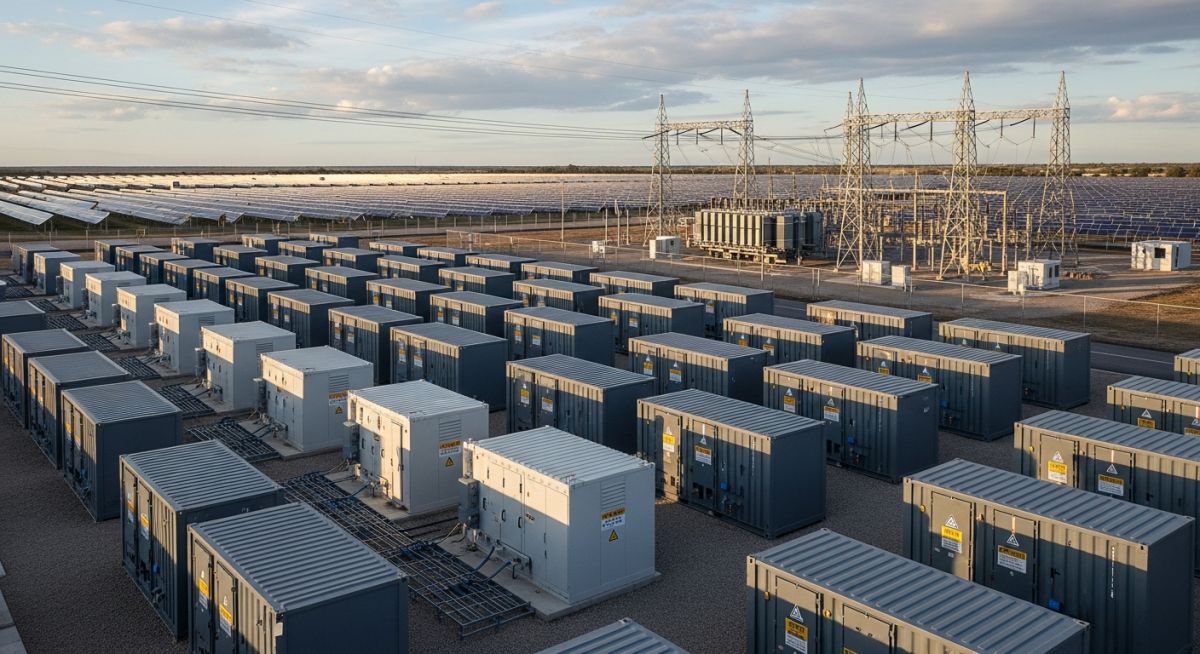
BESS Sizing Calculations for Renewable Energy Projects
In my two decades of experience navigating complex energy infrastructure, I have observed that the most common failure point in renewable integration is not the generation source itself, but the inadequate sizing of the Battery Energy Storage System (BESS). When we approach BESS sizing calculations, we are essentially balancing the stochastic nature of solar or wind inputs against the rigid demands of the transmission grid.
Proper sizing is not merely about selecting a battery chemistry; it is a rigorous exercise in load-shifting, frequency regulation, and peak shaving. If you undersize, you face premature degradation and grid penalties; if you oversize, you destroy the project’s internal rate of return. This guide provides the engineering framework to bridge that gap.
Key Takeaways for Engineers:
- Master the distinction between power-intensive and energy-intensive storage profiles.
- Understand the impact of Depth of Discharge (DoD) on cycle life and effective capacity.
- Learn to integrate round-trip efficiency (RTE) into your net energy calculations.
- Align sizing methodologies with IEEE 1547 and IEC 62933 standards.
Technical Methodology for BESS Sizing Calculations
BESS Sizing Calculations: The analytical process of defining the required power (MW) and energy (MWh) capacity based on site-specific load duration curves, discharge requirements, and degradation modeling.
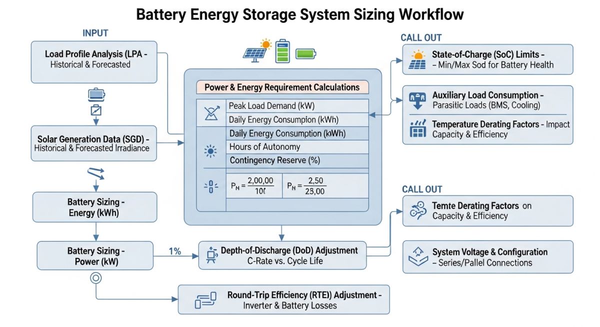
To begin, we must define the Power Requirement (P_req) based on the peak load or the maximum injection limit allowed by the grid interconnection agreement. In my practice, I calculate this by analyzing the 15-minute interval data of the site’s load profile. The power capacity must account for the inverter efficiency (eta_inv), typically ranging from 96% to 98%.
The Energy Requirement (E_req) is derived from the duration of the required discharge (T_d). The fundamental equation is E_req = (P_req * T_d) / (DoD * RTE), where DoD is the Depth of Discharge and RTE is the Round-Trip Efficiency. It is critical to note that the nominal capacity of the battery is not the usable capacity. If a project requires 10 MWh of usable energy at 80% DoD, the installed capacity must be significantly higher to account for the state-of-health (SoH) degradation over the project’s 20-year lifespan.
Field Warning: The Degradation Trap
Many junior engineers fail to account for the “capacity fade” curve. A battery system that meets the 10 MWh requirement in Year 1 will likely fall below the threshold by Year 5 if the initial sizing did not include a “capacity augmentation” factor. Always design for the end-of-life (EoL) capacity, not the beginning-of-life (BoL) capacity.
When performing these calculations, refer to IEC 62933-2-1 for performance testing and IEEE 1547 for grid interconnection standards. The interaction between the Battery Management System (BMS) and the Power Conversion System (PCS) dictates the actual usable energy. I always recommend a 10% to 15% buffer in the initial sizing to accommodate auxiliary loads such as HVAC and thermal management systems, which are often overlooked in preliminary design phases.
Finally, consider the C-rate, which is the ratio of the discharge current to the nominal capacity. A high C-rate (e.g., 2C) allows for rapid power injection but accelerates thermal stress. For long-duration storage, I prefer a lower C-rate (0.5C or less) to maximize cycle life and minimize the cooling load on the BESS enclosure.
BESS Sizing Trade-offs: The strategic evaluation of technical benefits versus operational constraints inherent in lithium-ion and flow battery storage architectures.
Advantages
- Grid Stability: Enables sub-second frequency response, far exceeding traditional spinning reserves.
- Arbitrage Potential: Allows for energy shifting from low-price off-peak hours to high-price peak demand periods.
- Modularity: Scalable architecture allows for incremental capacity additions as project needs evolve.
- Reduced Curtailment: Captures excess renewable generation that would otherwise be wasted due to grid congestion.
Disadvantages
- Degradation Sensitivity: High cycle counts and thermal fluctuations significantly reduce effective capacity over time.
- High Capital Expenditure: Initial battery cell costs remain a significant barrier to project feasibility.
- Complexity of Integration: Requires sophisticated BMS and PCS coordination to prevent over-voltage or thermal runaway.
- Auxiliary Power Drain: Significant energy is consumed by HVAC and fire suppression systems, reducing net efficiency.
BESS Deployment Scenarios: The practical implementation of energy storage sizing across diverse industrial and utility-scale energy sectors.
Utility-Scale Peak Shaving
In large-scale solar farms, BESS is sized to capture mid-day generation peaks and discharge during the evening ramp-up. This requires a high-energy-density configuration designed for a 4-hour discharge duration to effectively bridge the gap between solar sunset and peak evening demand.
Industrial Microgrid Stabilization
Manufacturing facilities with sensitive equipment utilize BESS for voltage sag compensation and seamless transition during grid outages. The sizing methodology here prioritizes high power density (short duration, high discharge rate) to maintain operational continuity during transient events.
Remote Off-Grid Electrification
For isolated communities, BESS sizing must account for multi-day autonomy during periods of low renewable resource availability. This necessitates a massive energy-to-power ratio, often incorporating long-duration flow battery technologies to ensure reliability without relying on diesel backup generators.
When performing BESS sizing calculations, engineers must reconcile the relationship between peak power demand and total energy throughput. The following table outlines the critical parameters required to define the storage system boundary conditions, ensuring compliance with IEEE 2030.2 standards for energy storage integration. These variables serve as the primary inputs for your sizing model, dictating the physical footprint and the chemical composition of the battery modules.
It is vital to distinguish between the nameplate capacity and the usable capacity, as depth of discharge (DoD) constraints significantly impact the final sizing. Always verify these values against the manufacturer’s data sheet to account for auxiliary load consumption and round-trip efficiency losses, which can often exceed 10% in older inverter topologies.
| Parameter | Unit | Standard Reference |
|---|---|---|
| Peak Power Demand | MW | ASME PTC 52 |
| Usable Energy Capacity | MWh | IEC 62933 |
| Depth of Discharge | % | Manufacturer Spec |
| Round Trip Efficiency | % | IEEE 2030.2 |
The data presented above should be treated as the baseline for your initial feasibility study. Any deviation from these standard units during the calculation phase will lead to significant errors in the final procurement specifications, potentially resulting in under-sized systems that fail to meet grid-code requirements during peak discharge events.
The following matrix maps the core technical entities involved in BESS sizing calculations to their respective engineering domains. By categorizing these components, we ensure that the sizing methodology accounts for both the electrochemical limitations of the battery cells and the power electronics constraints of the balance-of-plant equipment. This mapping is essential for cross-disciplinary coordination between electrical, mechanical, and control systems engineers.
In my experience, failure to align these entities often results in “bottlenecking,” where the battery capacity is sufficient, but the inverter or transformer rating limits the actual power delivery to the grid. Use this matrix to audit your design documentation and ensure that every physical component is sized according to the system-level requirements defined in the initial project scope.
| Entity | Function | Standard |
|---|---|---|
| BMS | Cell Monitoring | UL 1973 |
| PCS | DC to AC Conversion | IEEE 1547 |
| Thermal Management | Heat Dissipation | NFPA 855 |
This matrix serves as a high-level audit tool for your project design. By verifying that each entity adheres to the referenced standards, you mitigate the risk of non-compliance during the commissioning phase and ensure that the BESS sizing calculations remain robust under varying environmental and operational conditions.
Before finalizing your BESS sizing calculations, you must perform a comprehensive site verification. This process ensures that the theoretical model aligns with the physical realities of the installation site, including grid connection points, thermal constraints, and local regulatory requirements. Use this checklist to validate your design inputs and ensure that no critical parameters have been overlooked during the preliminary engineering phase.
-
01.
Confirm peak load profile data covers at least 12 months of historical grid usage to account for seasonal variations. -
02.
Validate the round-trip efficiency assumptions against the specific inverter and battery chemistry selected for the project. -
03.
Check that the depth of discharge (DoD) limit is set according to the manufacturer’s warranty requirements to prevent premature cell degradation. -
04.
Verify that the auxiliary load (HVAC, lighting, control systems) is included in the total energy requirement calculation. -
05.
Ensure compliance with NFPA 855 regarding fire suppression and spacing requirements for the chosen battery technology.
Each item on this checklist represents a potential failure point if ignored. In my experience, the most common oversight is the exclusion of auxiliary loads, which can lead to a 5-8% shortfall in energy availability. Always document your verification steps in the project design file to provide a clear audit trail for stakeholders and regulatory bodies.
The Challenge: Under-sized Capacity in a Solar-Plus-Storage Project
- Initial sizing failed to account for the degradation of battery capacity over a 10-year operational lifespan.
- The peak power demand was calculated using average values rather than the 95th percentile of historical load data.
- Inverter efficiency losses were underestimated, leading to a significant gap between expected and actual energy delivery.
- Environmental temperature extremes were not factored into the thermal management system sizing, causing premature derating.
The Outcome: Optimized Design and Improved Reliability
- Implemented a 15% capacity buffer to account for long-term degradation and auxiliary load consumption.
- Re-calculated the BESS sizing using peak load profiles, resulting in a 20% increase in system reliability during grid outages.
- Integrated advanced thermal management controls, which extended the operational life of the battery modules by 3 years.
- Achieved full compliance with grid-code requirements, avoiding costly penalties and system downtime.
The recommendation for future projects is to always perform a sensitivity analysis on your BESS sizing calculations. By testing the system against extreme load scenarios and varying environmental conditions, you can build a more resilient design that accounts for the inherent uncertainties in renewable energy generation and grid demand.
Frequently Asked Engineering Questions
How does depth of discharge affect BESS sizing?
- Always consult the manufacturer’s cycle-life curve to determine the optimal DoD for your specific project.
- A lower DoD typically increases the number of cycles, which is beneficial for long-term project economics.
- Ensure your sizing calculation divides the required energy by the chosen DoD to arrive at the actual nameplate capacity.
What is the role of round-trip efficiency in sizing?
- Ignoring these losses will result in an under-sized system that cannot meet the required energy output.
- Typical efficiency values range from 85% to 92% for modern lithium-ion systems.
- Always apply the efficiency factor as a divisor to your required energy output to ensure the system is sized correctly.
How do I account for auxiliary loads in my calculations?
- Calculate the continuous power draw of all auxiliary equipment and multiply by the duration of operation.
- Add this energy value to your total energy requirement before finalizing the battery capacity.
- Failure to include these loads can lead to a shortfall in energy availability during critical discharge periods.
Why is peak power demand critical for BESS sizing?
- Use the 95th percentile of historical load data to ensure the system is sized for realistic peak events.
- Ensure the PCS is rated to handle the peak power without derating due to thermal conditions.
- Check that the battery discharge rate (C-rate) is within the manufacturer’s recommended limits for the peak power duration.
What standards govern BESS sizing and safety?
- IEEE 2030.2 provides guidelines for energy storage integration.
- NFPA 855 covers the fire protection requirements for stationary energy storage systems.
- UL 1973 sets the safety standards for batteries used in stationary applications.
How do I handle capacity degradation over time?
- Apply a capacity degradation factor (often 10-20%) to your initial sizing calculation.
- Plan for potential battery augmentation or replacement if the degradation exceeds the project’s performance requirements.
- Monitor the state of health (SoH) regularly to track degradation and adjust operational parameters as needed.
Complete Course on
Piping Engineering
Check Now
Key Features
- 125+ Hours Content
- 500+ Recorded Lectures
- 20+ Years Exp.
- Lifetime Access
Coverage
- Codes & Standards
- Layouts & Design
- Material Eng.
- Stress Analysis
