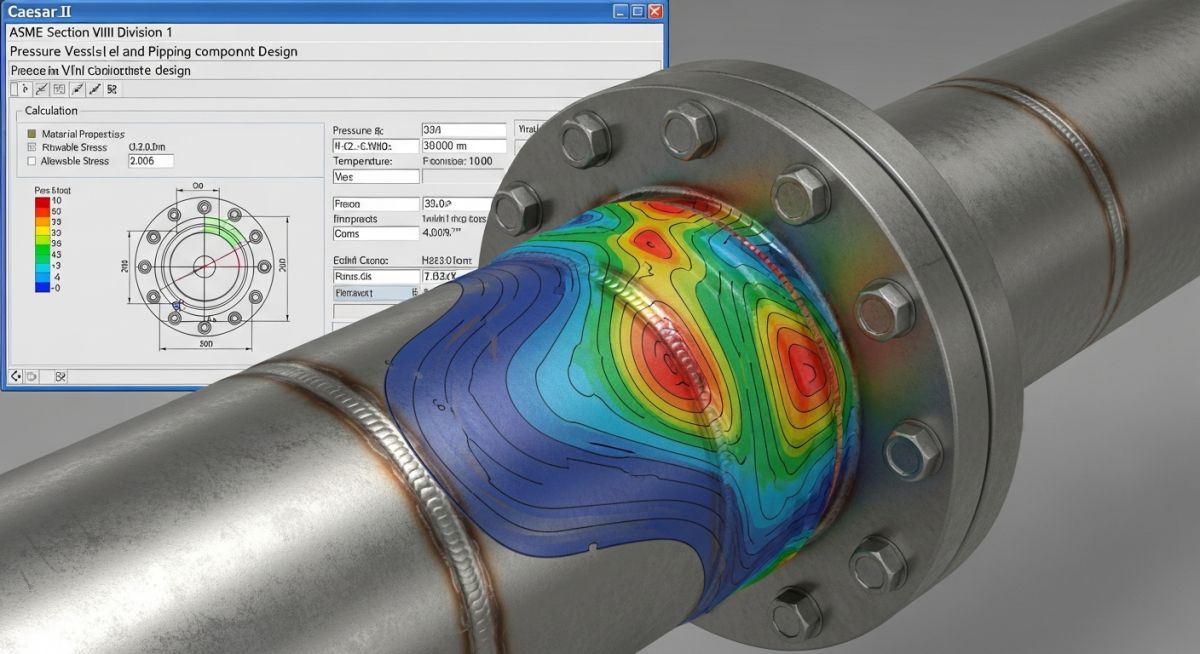
ASME Section VIII Flange Leakage Checking Method in Caesar II
In my 20+ years of piping stress analysis, I have witnessed countless field failures that could have been easily avoided. The most common culprit is not the pipe wall bursting, but rather the silent, hazardous failure of bolted flange joints. When high-temperature piping systems expand, they exert massive bending moments and axial forces on rigid flange connections. If you only design flanges for internal pressure, you are missing more than half of the physical reality.
Using Caesar II to perform flange leakage checks according to ASME Section VIII Division 1 is the industry-standard way to guarantee that your joints remain tight under all operating conditions. This method converts complex external piping loads into a single, manageable equivalent pressure, which is then compared directly against the flange’s maximum allowable working pressure.
Key Takeaways from This Guide
- Understand the mathematical foundation of the Kellogg Equivalent Pressure method.
- Learn how to configure and run the Flange Leakage module in Caesar II.
- Discover how to interpret stress reports to prevent hazardous emissions.
- Identify the exact parameters needed from gasket and bolt specifications.
ASME Section VIII Flange Leakage Checking in Caesar II
The core of the ASME Section VIII flange leakage checking method relies on the Kellogg Equivalent Pressure Method. This approach simplifies the complex, non-axisymmetric stress state caused by external bending moments and axial forces. It translates these forces into an imaginary, uniform internal pressure that would cause the same longitudinal stress at the flange hub.
The Equivalent Pressure Equation
The total equivalent pressure (Peq) is calculated using the following plain-text formula:
Where:
– Peq is the total equivalent pressure (psi or MPa).
– Pd is the internal design pressure of the system.
– F is the external axial force acting on the flange joint.
– M is the external bending moment acting on the flange joint.
– G is the gasket reaction diameter, defined by ASME B16.5 and ASME Section VIII rules.
– pi is the mathematical constant approximately equal to 3.14159.
Implementing the Method in Caesar II
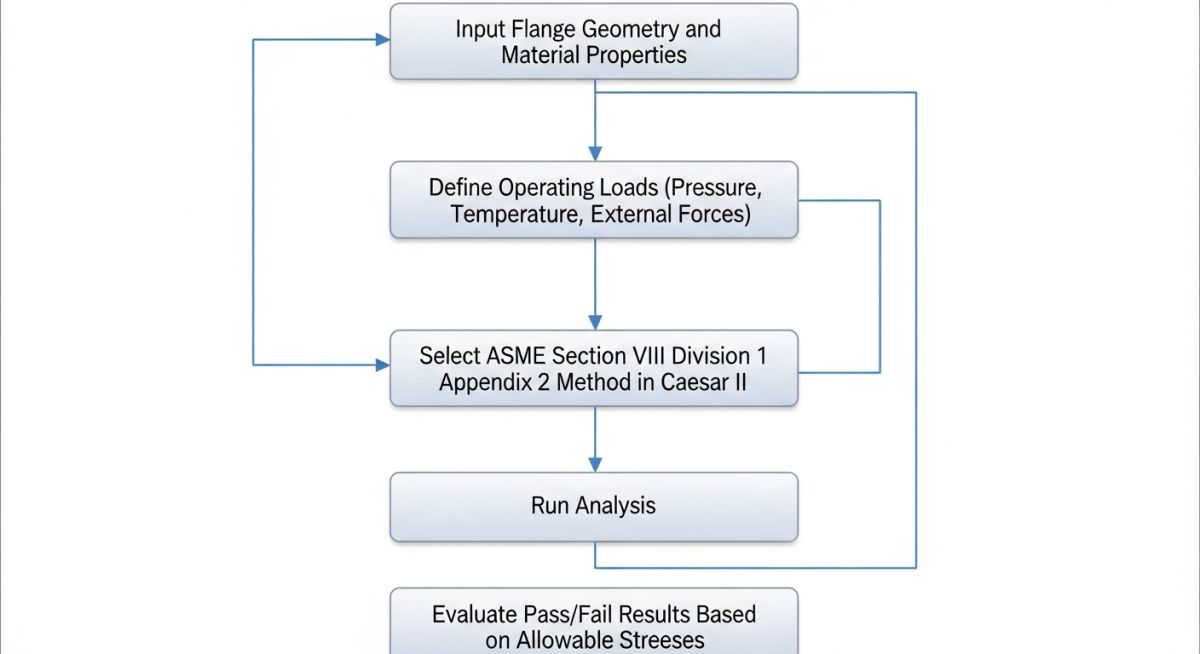
To perform this check in Caesar II, you must access the “Flange Leakage” utility. First, ensure your static analysis run is complete and you have active load cases for Sustained (SUS), Expansion (EXP), and Operating (OPE) conditions. The software extracts the forces and moments at the specific node where the flange is modeled, applies the gasket dimensions you input, and automatically computes the equivalent pressure for each load case.
| Flange Class (ASME B16.5) | Nominal Size (NPS) | Material Group | Max Allowable Pressure at 100°F (psi) | Typical Gasket Diameter G (in) |
|---|---|---|---|---|
| Class 150 | 6 | Group 1.1 (Carbon Steel) | 285 | 7.50 |
| Class 300 | 6 | Group 1.1 (Carbon Steel) | 740 | 7.50 |
| Class 600 | 6 | Group 1.1 (Carbon Steel) | 1480 | 7.50 |
| Class 900 | 6 | Group 1.1 (Carbon Steel) | 2220 | 7.50 |
| Technical Entity | Acronym | Physical Parameter | Standard Reference |
|---|---|---|---|
| Equivalent Pressure | Peq | Combined internal and external load pressure | ASME Sec VIII Div 1 App 2 |
| Gasket Reaction Diameter | G | Effective diameter of gasket sealing force | ASME Section VIII Appendix 2 Table 2-5.2 |
| Flange Rating Limit | Pmax | Maximum pressure rating at operating temperature | ASME B16.5 Table 2 |
ASME Section VIII Flange Leakage Checking in Caesar II Checklist
Before finalizing your stress analysis report, you must verify that the physical parameters entered into Caesar II match the actual field construction drawings. Discrepancies here can lead to catastrophic joint failures during commissioning.
Verification Checkpoints
-
Gasket Dimensions: Verify that the gasket outer diameter, inner diameter, and effective width (b) match the manufacturer’s data sheet exactly.
-
Flange Material Group: Confirm that the flange material group in Caesar II matches the piping specification (e.g., A105 for Group 1.1).
-
Operating Temperature: Ensure the maximum operating temperature is used to determine the allowable pressure limit, as flange ratings drop significantly at high temperatures.
-
Load Case Selection: Verify that both Sustained (SUS) and Operating (OPE) load cases are selected for the leakage evaluation.
-
Bolt Torque Values: Cross-reference the calculated bolt load with the field torque procedures to ensure the gasket is properly seated without crushing.
Field Case Study: Real-World Application
The Problem: High-Pressure Steam Line Leakage
During the commissioning of a high-pressure steam line (600 psi, 750°F), a Class 600 flanged joint at a turbine inlet began leaking severely. The initial piping stress analysis had passed all code stress checks under ASME B31.3. However, the designer had completely omitted the flange leakage check, assuming that because the pipe stress was low, the flanges were safe.
The Solution & Outcome
I was called to the site to troubleshoot. We modeled the exact flange assembly in Caesar II and ran the ASME Section VIII flange leakage module. The analysis revealed that thermal expansion of the long vertical run was generating a bending moment of 45,000 ft-lb at the turbine nozzle. This moment translated to an equivalent pressure of 1,850 psi—far exceeding the Class 600 flange rating of 1,200 psi at 750°F.
We resolved the issue by adding an expansion loop to absorb the thermal growth, reducing the bending moment to 12,000 ft-lb. This brought the equivalent pressure down to 950 psi, safely below the flange rating. The joint was re-torqued, and the subsequent hydrotest and hot operations passed with zero leakage.
Direct Recommendation: Always perform a dedicated flange leakage check for any piping system operating above Class 150 or at temperatures exceeding 400°F. Relying solely on pipe stress compliance is a recipe for field failures.
Frequently Asked Engineering Questions
What is the difference between ASME Section VIII and NC 3658 flange checks?
Why does Caesar II show a flange failure when the pipe stress is only 40% of allowable?
How do I find the gasket reaction diameter (G) for my analysis?
Can I use the Kellogg method for non-standard custom flanges?
Does Caesar II account for gasket relaxation over time?
What should I do if my flange fails the leakage check?
Complete Course on
Piping Engineering
Check Now
Key Features
- 125+ Hours Content
- 500+ Recorded Lectures
- 20+ Years Exp.
- Lifetime Access
Coverage
- Codes & Standards
- Layouts & Design
- Material Eng.
- Stress Analysis
