Understanding the Critical Role of Y Factor in ASME B31.3
In my 20 years of experience designing high-temperature piping systems for refineries and petrochemical plants, I have seen minor design oversights lead to catastrophic field failures. One of the most misunderstood parameters in the ASME B31.3 wall thickness equation is the Y factor. This simple-looking coefficient is the thin line between an optimized, safe piping system and a ticking time bomb operating in the creep range.
When designing piping for ambient conditions, we rely on elastic stress distribution. However, as operating temperatures climb into the creep regime, materials begin to behave plastically. The Y factor is the code’s mathematical bridge that transitions our calculations from pure elastic theory to plastic stress redistribution. Ignoring its temperature-dependent nature can lead to under-designed pipe walls, accelerated creep-rupture, and premature system failure.
Key Engineering Takeaways
- The Y factor is not a constant; it varies dynamically from 0.4 to 0.7 based on material structure and design temperature.
- At lower temperatures, Y represents the elastic stress distribution across the pipe wall thickness.
- At elevated temperatures, Y increases to account for plastic deformation and creep stress relaxation.
- Incorrect selection of the Y factor directly violates ASME B31.3 compliance and compromises structural integrity.
Complete Course on
Piping Engineering
Check Now
Key Features
- 125+ Hours Content
- 500+ Recorded Lectures
- 20+ Years Exp.
- Lifetime Access
Coverage
- Codes & Standards
- Layouts & Design
- Material Eng.
- Stress Analysis
Why Y Factor in ASME B31.3 Matters
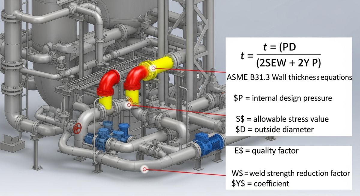
To understand why the Y factor is so important, we must look at the fundamental equation for pressure design thickness (t) under ASME B31.3 Paragraph 304.1.2:
Where:
P = Internal design gage pressure
D = Outside diameter of the pipe
S = Allowable stress value for the material from Table A-1
E = Quality factor from Table A-1A or Table A-1B
W = Weld joint strength reduction factor
Y = Coefficient from Table 304.1.1 (The Y Factor)
In an elastic state (at lower temperatures), the stress across a thick-walled cylinder is non-uniform. The hoop stress is highest at the inner bore and lowest at the outer surface. This is represented by Lame’s equations. When we design in this regime, a Y factor of 0.4 acts as an interpolation coefficient to approximate this non-linear stress distribution.
However, when the operating temperature enters the creep range, the material undergoes continuous plastic deformation under constant stress. This plastic flow relaxes the highly stressed inner fibers and shifts the load toward the outer fibers. Over time, the stress distribution across the pipe wall becomes almost completely uniform.
To reflect this uniform stress state, the Y factor increases. For ferritic steels, it transitions from 0.4 to 0.5, and eventually up to 0.7 for other materials at extreme temperatures. If you fail to update the Y factor in your calculations, you are assuming the material is still behaving elastically, which leads to an incorrect calculation of the required wall thickness.
Material Classifications and Temperature Limits
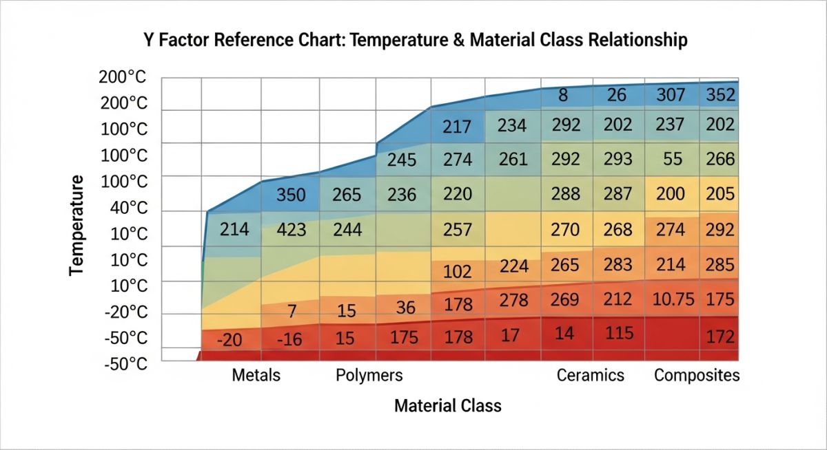
The Y factor is highly dependent on the microstructure of the material. ASME B31.3 Table 304.1.1 divides materials into distinct groups: Ferritic steels, Austenitic steels, Other ductile materials, and Cast iron. Cast iron has a Y factor of 0.0 because it is a brittle material that does not undergo plastic stress redistribution; it fails in a brittle manner before any creep-induced relaxation can occur.
Applying Y Factor in ASME B31.3 Calculations
When performing wall thickness calculations, you must reference the exact values from ASME B31.3 Table 304.1.1. Below is a structured reference table showing how the Y factor changes as design temperatures rise.
| Material Type | ≤ 482°C (≤ 900°F) | 510°C (950°F) | 538°C (1000°F) | 566°C (1050°F) | 593°C (1100°F) | ≥ 621°C (≥ 1150°F) |
|---|---|---|---|---|---|---|
| Ferritic Steels | 0.4 | 0.5 | 0.7 | 0.7 | 0.7 | 0.7 |
| Austenitic Steels | 0.4 | 0.4 | 0.4 | 0.4 | 0.5 | 0.7 |
| Nickel Alloys | 0.4 | 0.4 | 0.4 | 0.4 | 0.4 | 0.5 |
| Other Ductile Materials | 0.4 | 0.4 | 0.4 | 0.4 | 0.4 | 0.4 |
| Cast Iron | 0.0 | N/A | N/A | N/A | N/A | N/A |
For intermediate temperatures, ASME B31.3 allows linear interpolation between the values shown in the table. This is a critical step that many junior engineers miss, leading to either over-designed piping or non-compliant wall thicknesses.
To help you navigate the relationship between material grades, temperature thresholds, and code references, I have compiled this technical mapping matrix.
| Material Grade | Common Standard | Creep Threshold | Y Factor at Threshold | ASME B31.3 Reference |
|---|---|---|---|---|
| Carbon Steel (A106 Gr. B) | ASTM A106 | 371°C (700°F) | 0.4 | Table 304.1.1 / Table A-1 |
| Low Alloy Steel (P22) | ASTM A335 | 454°C (850°F) | 0.4 to 0.5 (Interpolated) | Table 304.1.1 / Table A-1 |
| Austenitic SS (316H) | ASTM A312 | 538°C (1000°F) | 0.4 | Table 304.1.1 / Table A-1 |
| Alloy 800H (UNS N08810) | ASTM B407 | 593°C (1100°F) | 0.4 to 0.5 (Interpolated) | Table 304.1.1 / Table A-1 |
Verifying Y Factor in Piping Design
Before releasing any piping isometric drawings or stress analysis reports for construction, I always run through a strict verification checklist. This ensures that the Y factor used in the calculations matches the actual physical properties of the piping system under design conditions.
Y Factor Design Verification Checklist
-
Verify Material Grouping: Cross-reference the specified material grade (e.g., ASTM A335 P91) with the material classifications in ASME B31.3 Table 304.1.1.
-
Confirm Design Temperature: Ensure the design temperature used in the wall thickness calculation matches the process design conditions, not just the normal operating temperature.
-
Check for Linear Interpolation: If the design temperature falls between the values listed in Table 304.1.1, verify that linear interpolation was performed correctly. Do not round up or down to the nearest table value.
-
Validate Thickness-to-Diameter Ratio: Confirm that the ratio of design thickness to outside diameter (t/D) is less than 0.16. If t/D is greater than or equal to 0.16, the standard wall thickness equation and standard Y factors do not apply; you must use the thick-wall equations in Paragraph 304.1.2(b).
-
Software Input Audit: Audit the piping stress analysis software (e.g., CAESAR II) and 3D modeling software to ensure the Y factor has not been hardcoded to a default value of 0.4.
Field Case Study: High-Temperature Steam Line Failure Analysis
The Problem: Creep Deformation in a Superheated Steam Line
During a routine turnaround at a combined-cycle power plant, inspectors discovered localized bulging and micro-cracking on a high-pressure superheated steam line. The line was constructed from ASTM A335 Grade P22 (2.25Cr-1Mo) low-alloy steel and operated at 540°C (1004°F) with an internal design pressure of 4.2 MPa.
Upon reviewing the original design calculations, our forensic team discovered a critical oversight by the engineering contractor. The software model had defaulted to properties for a line operating below the creep threshold (~480°C):
- Incorrect Y Factor: A default value of Y = 0.4 was used instead of interpolating the elevated temperature factor of Y = 0.5 as required for 540°C per ASME B31.3 Table 304.1.1.
- Overestimated Allowable Stress (S): Crucially, the calculation sheet applied allowable stress values corresponding to non-creep temperatures (480°C), drastically overestimating the material strength.
Although reducing Y in the ASME formula mathematically increases the calculated wall thickness, using S values for 480°C severely underestimated the actual wall thickness required at 540°C. This combination left the pipe wall significantly under-designed for primary hoop stress at elevated temperatures, triggering accelerated creep deformation within just 18 months of operation.
🔍 Forensic Analysis: Why Was the Incorrect Allowable Stress Selected?
In high-temperature piping design, selecting an incorrect allowable stress value (S) is rarely intentional. Forensic reviews usually reveal one of the following root causes:
- Default Software Material Libraries: Stress analysis programs (like CAESAR II or AutoPIPE) or custom Excel calculation sheets often default to base material properties at ambient or lower threshold temperatures (~480°C) if the user forgets to manually override the operating/design temperature cards.
- Copy-Pasting Calculation Templates: Designers frequently reuse previous line calculations or legacy templates from lower-temperature services, failing to update the temperature-dependent stress values from ASME B31.3 Table A-1.
- Confusing Normal Operating vs. Design Excursion Temps: The calculations were performed using normal steady-state operating conditions rather than accounting for peak steam temperature excursions during plant startup or transient upsets that pushed the material deep into the creep range.
- Misunderstanding the Creep Cutoff Limit: For P22 steel, 482°C marks the critical boundary where creep mechanism dominates failure modes. A designer unfamiliar with high-temperature metallurgy might assume allowable stress scales linearly, missing the sharp drop in material strength above 500°C.
💡 Engineering Insight: Understanding the Y Factor Paradox
In the ASME B31.3 pressure design formula t = (P × D) / [2 × (S × E + P × Y)], the Y factor increases with temperature (from 0.4 up to 0.7) to account for plastic stress redistribution in the creep regime. Because Y is in the denominator, a higher Y actually yields a slightly thinner calculated minimum thickness for a given allowable stress.
However, when temperatures reach 540°C, the allowable stress S drops far more aggressively than Y increases. Failing to adjust both parameters simultaneously results in an unsafe design that severely underpredicts wall thinning and creep risk.
The Outcome: Recalculation & Remediation
Leading the forensic engineering response, our team re-evaluated the pipe sizing using the fully derated allowable stress S and corrected Y = 0.5 as per ASME B31.3 Table 304.1.1 for 540°C.
The comprehensive recalculation revealed that the actual required pipe wall thickness was substantially greater than what had been installed. We immediately replaced the damaged piping run with a heavier schedule section suited for severe creep service.
To protect against future degradation, high-temperature strain gauges and creep monitoring points were installed. The line has now been operating safely and reliably for over five years without further dimensional distortion or cracking.
Key Takeaway for Engineers: Never rely on default software parameters when operating near or inside the material’s creep regime. Always verify both the allowable stress (S) and the coefficient (Y) against code tables at actual design temperatures. Treating these parameters as static defaults can severely compromise high-temperature piping integrity.
Frequently Asked Engineering Questions
What is the physical meaning of the Y factor in ASME B31.3?
How do I calculate the Y factor for intermediate temperatures?
Why is the Y factor for cast iron always 0.0?
What happens if the t/D ratio is greater than or equal to 0.16?
Can I use a Y factor of 0.4 for all carbon steel piping?
How does the Y factor affect the calculated minimum wall thickness?
===FAQ_BLOCK===