What is ASME B31.3 Pressure Leak Test Requirements
In my 20-plus years of standing on muddy refinery sites and commissioning complex chemical plants, I have seen many engineers treat the pressure test as a mere administrative checkbox. This is a dangerous mistake. A pressure leak test is the final, definitive line of defense between a safe, operational facility and a catastrophic release of hazardous fluid. When you pressurize a piping system to its limits, you are testing the integrity of every weld, gasket, and valve body.
The ASME B31.3 Process Piping Code provides strict guidelines on how these tests must be calculated, prepared, and executed. Whether you are performing a hydrostatic test with water or a pneumatic test with nitrogen, you must understand the underlying physics and code boundaries to prevent catastrophic field failures.
Key Takeaways
- Hydrostatic testing is the default and safest method, requiring a minimum of 1.5 times the design pressure adjusted for temperature.
- Pneumatic testing is highly hazardous due to stored elastic energy and is restricted to systems where moisture cannot be tolerated.
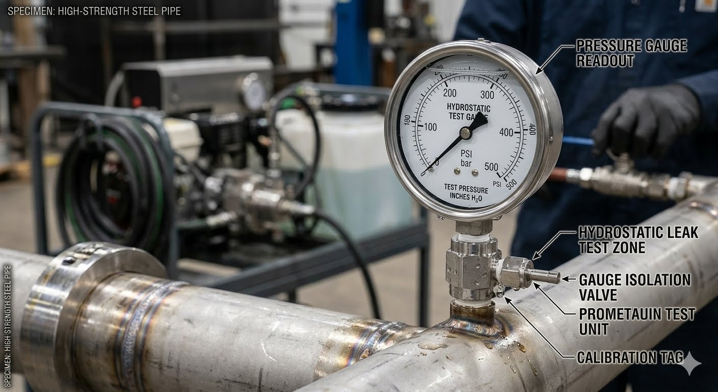
- All pressure gauges must be calibrated, and the test system must be completely isolated from sensitive equipment like control valves and rotating machinery.
How to Perform ASME B31.3 Pressure Leak Test
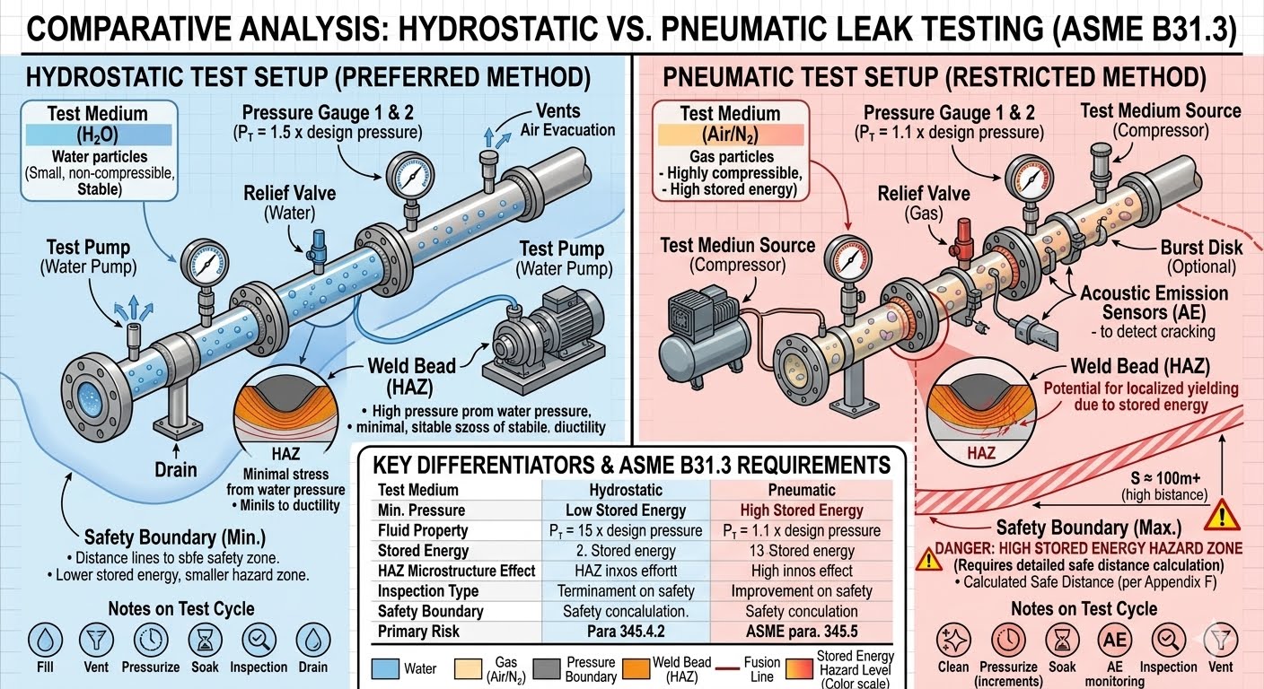
When preparing for an ASME B31.3 pressure leak test, the first step is determining which test method is appropriate. The code recognizes several types of leak tests: hydrostatic, pneumatic, hydro-pneumatic, and alternative leak tests. Hydrostatic testing is always the preferred method because water is virtually incompressible, meaning it stores very little energy under pressure.
Hydrostatic Test Pressure Calculation
The minimum hydrostatic test pressure for metallic piping is calculated using the following formula from ASME B31.3 Paragraph 345.4.2:
Where:
- Pt = minimum hydrostatic test gauge pressure (psi or MPa)
- P = internal design gauge pressure (psi or MPa)
- St = allowable stress value at test temperature (psi or MPa)
- S = allowable stress value at design temperature (psi or MPa)
If the ratio of St to S exceeds 6.5, the ratio used in the calculation must be limited to 6.5. This prevents over-stressing the piping components during the test. In my experience, you must also ensure that the test pressure does not produce a hoop stress exceeding 90% of the material’s yield strength at the test temperature.
Never conduct a hydrostatic or pneumatic test at temperatures near or below the material’s ductile-to-brittle transition temperature. For carbon steels, the test fluid and piping temperature should ideally be kept above 17 degrees Celsius (62 degrees Fahrenheit) to eliminate the risk of brittle fracture under high stress.
Pneumatic Test Pressure Calculation
Pneumatic testing is highly hazardous because compressed gas stores a massive amount of expansion energy. Under ASME B31.3 Paragraph 345.5, the pneumatic test pressure is calculated as:
Because of the inherent danger, a preliminary leak test must be performed at 25 psi (170 kPa) or 10% of the target test pressure, whichever is lower. This preliminary step allows you to locate major leaks safely before ramping up to full test pressure in gradual increments.
Standard Parameters for ASME B31.3 Pressure Leak Test
To ensure consistency and safety across projects, I always refer to a structured set of parameters. The table below outlines the key differences and operational limits for hydrostatic and pneumatic testing under the ASME B31.3 standard.
| Parameter | Hydrostatic Testing | Pneumatic Testing |
|---|---|---|
| Minimum Test Pressure | 1.5 times Design Pressure (adjusted for temperature) | 1.1 times Design Pressure |
| Test Medium | Water (or alternative non-toxic liquid) | Air, Nitrogen, or non-flammable gas |
| Minimum Hold Time | 10 minutes (prior to inspection) | 10 minutes (prior to inspection) |
| Pressure Relief Device | Required if over-pressurization is possible | Mandatory (set at 110% of test pressure or design pressure + 50 psi) |
| Stored Energy Hazard | Low (Incompressible fluid) | Extremely High (Compressible gas) |
Technical Mapping & Specifications Matrix
The following matrix maps the core technical entities, structural acronyms, and physical parameters associated with pressure testing to their respective code references.
| Entity / Acronym | Physical Parameter | ASME B31.3 Reference | Engineering Significance |
|---|---|---|---|
| MAOP | Maximum Allowable Operating Pressure | Paragraph 345.1 | Defines the upper limit of pressure during normal operations. |
| S_t / S | Stress Ratio (Test to Design) | Paragraph 345.4.2 | Compensates for reduced material strength at elevated operating temperatures. |
| S_y | Specified Minimum Yield Strength | Paragraph 345.2.1 | Ensures the test pressure does not cause permanent plastic deformation. |
| PRD | Pressure Relief Device | Paragraph 345.5.2 | Prevents catastrophic over-pressurization during pneumatic testing. |
Mandatory Checklist for Piping Pressure Tests
Before you sign off on any pressure test, you must verify that the field crew has completed all preparatory steps. Skipping even a minor step can lead to gauge damage, system contamination, or severe safety hazards. Use this checklist on your next project site.
Pre-Test Field Verification Checklist
-
System Isolation: Verify that all control valves, orifice plates, and expansion joints are removed or isolated with rated blind flanges. -
Spring Hangers: Ensure all spring hangers and piping supports are locked in their cold positions to handle the extra weight of the water. -
High-Point Vents: Confirm that high-point vents are open during filling to completely purge air from the system. -
Gauge Calibration: Verify that at least two pressure gauges are installed, calibrated within the last 6 months, and have a range of 1.5 to 4 times the test pressure. -
Safety Perimeter: Establish a clear exclusion zone with barricades and warning signs to keep non-essential personnel away from pressurized lines.
Field Case Study: Real-World Application
The Problem: Catastrophic Flange Failure During Hydrotest
During the commissioning of a high-pressure gas processing unit, a 12-inch Class 600 carbon steel piping system was subjected to a hydrostatic test. The design pressure was 1,200 psi, making the target test pressure 1,800 psi. The field team filled the system with water but failed to open the high-point vents completely, trapping a significant volume of air.
As the pressure reached 1,500 psi, the trapped air compressed, storing massive potential energy. A sudden pressure spike occurred due to solar heating of the piping, causing a flange gasket to blow out. The stored energy of the compressed air released violently, throwing metal fragments across the unit and damaging adjacent instrumentation.
The Outcome & Resolution
I was called to investigate the incident. We identified two primary failures: trapped air and lack of temperature monitoring. To resolve this, we implemented a strict venting protocol requiring water to flow continuously from all high-point vents before closing them. We also installed a calibrated pressure relief valve on the test manifold set at 1,850 psi to prevent thermal expansion over-pressurization.
The system was re-tested successfully with zero trapped air. The pressure was held at 1,800 psi for 30 minutes with no pressure drop, proving the structural integrity of the piping system and satisfying the ASME B31.3 requirements.
My direct recommendation for any high-pressure test is to always use a dedicated, calibrated relief valve on your test pump manifold. Never rely solely on manual valves to control pressure spikes caused by environmental temperature changes.
Frequently Asked Engineering Questions
What is the minimum hold time for an ASME B31.3 pressure leak test?
Can we use a pneumatic test instead of a hydrostatic test?
What is the temperature limit for water used in a hydrostatic test?
Are weld joints allowed to be painted before a leak test?
What is an alternative leak test under ASME B31.3?
How many pressure gauges are required for a code-compliant test?


