How Industrial Pressure Regulators Work and Solve Piping Challenges
In my 20 years of commissioning piping systems across petrochemical plants and gas distribution networks, I have seen many engineers treat pressure regulators as simple, set-and-forget commodities. This is a costly mistake. A poorly selected regulator can destabilize an entire process loop, cause severe piping vibration, or lead to catastrophic overpressure events. Unlike control valves that require external pneumatic or electrical signals, pressure regulators are self-contained, relying entirely on the energy of the process fluid to modulate flow.
Understanding the delicate balance of forces inside these mechanical devices is key to achieving stable system pressure. Whether you are managing a high-pressure nitrogen blanketing system or a municipal water distribution line, selecting the correct regulator type and sizing it accurately is the difference between a smooth operation and a maintenance nightmare.
Key Takeaways
- Master the mechanical force balance that governs all direct-acting and pilot-operated regulators.
- Learn how to calculate and mitigate droop, lockup, and choked flow conditions.
- Understand the critical differences between diaphragm and piston sensing elements for high-pressure applications.
- Implement a robust field commissioning protocol to prevent diaphragm rupture and seat damage.
Complete Course on
Piping Engineering
Check Now
Key Features
- 125+ Hours Content
- 500+ Recorded Lectures
- 20+ Years Exp.
- Lifetime Access
Coverage
- Codes & Standards
- Layouts & Design
- Material Eng.
- Stress Analysis
How Do Industrial Pressure Regulators Work Safely?
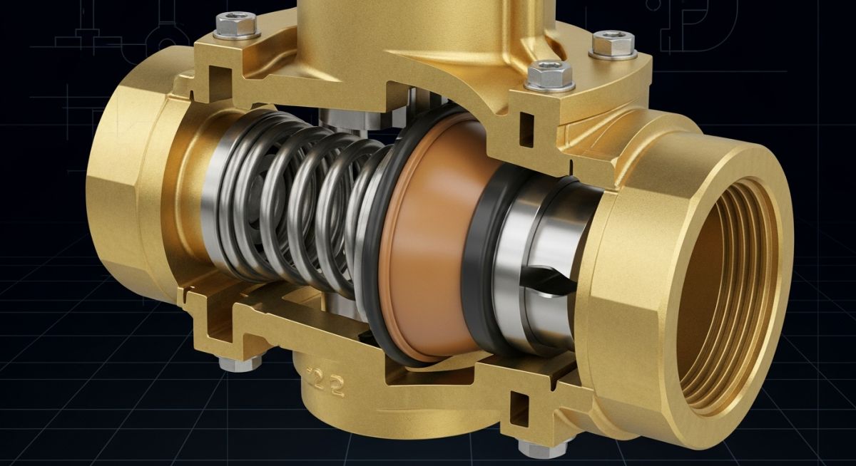
At its core, a pressure regulator operates on a simple force balance principle. The device consists of three primary components: the restricting element (the valve plug and orifice), the loading element (typically a compressed helical spring or a pressurized dome), and the measuring element (a flexible diaphragm or a piston).
The force balance equation governing a standard direct-acting, pressure-reducing regulator can be written as:
Where:
Fs is the downward force exerted by the adjustable range spring.
P2 is the downstream outlet pressure acting on the underside of the diaphragm.
Ad is the effective surface area of the sensing diaphragm.
Ff represents the frictional and dynamic forces acting on the valve stem and plug.
When downstream demand decreases, the pressure (P2) rises. This increase in pressure acts on the diaphragm, overcoming the spring force (Fs) and pushing the diaphragm upward. This movement moves the valve plug closer to the orifice seat, restricting the flow of fluid and restoring the downstream pressure to its setpoint. Conversely, an increase in downstream demand causes a drop in P2, allowing the spring to push the diaphragm down, opening the valve plug to allow more fluid to pass.
Never size a pressure regulator based on the nominal pipe size. An oversized regulator operates too close to its seat, causing the plug to hunt and cycle rapidly. This rapid cycling leads to severe pressure oscillations, accelerated seat wear, and premature diaphragm rupture. Always size the regulator for the minimum, normal, and maximum flow conditions.
Selecting Pressure Regulators for High Flow Systems
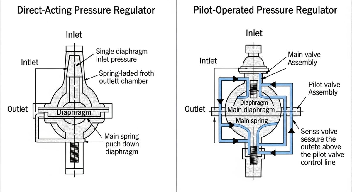
When designing high-flow systems, the choice between direct-acting and pilot-operated regulators is a critical decision. Direct-acting regulators are robust, fast-acting, and highly reliable. However, they suffer from a phenomenon known as “droop”—the decrease in outlet pressure below the setpoint as the flow rate increases. This occurs because the spring must extend to open the valve, which naturally reduces the spring force (Fs) it exerts.
For systems requiring precise pressure control across wide flow variations, pilot-operated regulators are the preferred choice. These devices utilize a small, highly sensitive pilot regulator to control the pressure loaded onto the main diaphragm. This design isolates the main diaphragm from downstream pressure fluctuations, virtually eliminating droop and providing a flat performance curve.
Sizing Calculations for Gas Pressure Regulators
To size a regulator for gas service, we must calculate the required flow coefficient (Cv) using the standard ISA 75.01 sizing equations. For non-choked gas flow, the equation is:
Where:
Q is the gas flow rate in standard cubic feet per hour (SCFH).
P1 is the absolute inlet pressure (psia).
Y is the expansion factor (typically 0.66 to 1.0).
x is the pressure drop ratio (delta P / P1).
G is the specific gravity of the gas (air = 1.0).
T is the absolute inlet temperature in Rankine (Fahrenheit + 460).
Z is the compressibility factor of the gas.
If the pressure drop ratio (x) exceeds the terminal pressure drop ratio (xT), choked flow occurs. Under choked conditions, the flow velocity reaches the speed of sound at the vena contracta, and further decreases in downstream pressure will not increase the flow rate. In my experience, operating a regulator in continuous choked flow leads to severe aerodynamic noise and rapid erosion of the trim.
The table below compares the operational characteristics of direct-acting and pilot-operated regulators. This data is compiled from field testing and manufacturer specifications in compliance with ASME B16.34.
| Performance Parameter | Direct-Acting Regulators | Pilot-Operated Regulators |
|---|---|---|
| Droop (Offset) | High (10% to 30% of setpoint) | Very Low (1% to 5% of setpoint) |
| Response Speed | Extremely Fast (Milliseconds) | Moderate (Seconds) |
| Minimum Pressure Drop | Low (No minimum required) | Requires minimum differential (typically 10-15 psi) |
| Mechanical Complexity | Low (Few moving parts) | High (Contains pilot, tubing, and filters) |
| Susceptibility to Particulates | Low | High (Requires fine upstream filtration) |
This matrix maps the core technical entities of pressure regulators, their physical parameters, and the governing industry standards.
| Technical Entity | Definition & Function | Physical Parameter | Governing Standard |
|---|---|---|---|
| Sensing Diaphragm | Converts downstream pressure into mechanical force. | Effective Area (sq. in.), Elastomer Temp Limits | ASME B31.3 |
| Control Spring | Provides the adjustable reference force to set the outlet pressure. | Spring Rate (lbs/in), Setpoint Range | ASTM A125 |
| Valve Trim (Plug/Seat) | Restricts fluid flow to modulate downstream pressure. | Flow Coefficient (Cv), Leakage Class | ANSI/FCI 70-2 |
| External Sensing Line | Pipes downstream pressure back to the diaphragm from a stable flow zone. | Tubing OD (typically 1/4″ or 3/8″) | API RP 551 |
Field Commissioning of Industrial Pressure Regulators
Before introducing process fluid into any newly installed regulator, a rigorous field verification must be performed. Skipping these steps often results in immediate diaphragm failure or seat damage due to construction debris.
Site Verification Checkpoints
-
Flow Direction Alignment: Verify that the flow arrow cast on the regulator body matches the actual process flow direction.
-
Sensing Line Location: Ensure the external sensing line is tapped at least 5 to 10 pipe diameters downstream of the regulator, in a straight run of pipe free from turbulence-inducing fittings.
-
Upstream Filtration: Confirm that a 40-micron (or finer) strainer is installed upstream of the regulator to protect the trim from welding slag and pipe scale.
-
Vent Line Routing: Verify that the regulator spring case vent is pointed downward to prevent water ingress, or piped to a safe header if handling hazardous gases.
-
Overpressure Protection: Ensure a safety relief valve is installed downstream of the regulator, set to protect the downstream piping from regulator failure.
Field Case Study: Real-World Application
The Problem: Severe Droop in Nitrogen Blanketing System
At a chemical storage terminal, a direct-acting pressure regulator was installed to control nitrogen blanket pressure on a low-pressure solvent tank. The target setpoint was 5 inches of water column (in. w.c.). During peak pump-out operations, the nitrogen demand spiked rapidly. The direct-acting regulator suffered from severe droop, allowing the tank pressure to fall to negative 2 inches of water column. This vacuum condition pulled atmospheric air into the tank, creating an explosive mixture and triggering emergency shutdown systems.
The Solution: Upgrading to a Pilot-Operated Regulator
I was called to troubleshoot the system. After analyzing the flow rates, I calculated that the direct-acting regulator was operating at the limit of its spring range, causing a 140% droop during peak flow. I recommended replacing the unit with a pilot-operated regulator. The pilot-operated design utilized a highly sensitive pilot to amplify the pressure signal, maintaining the downstream pressure within 0.2 inches of water column across the entire flow range.
Following the installation of the pilot-operated regulator, the nitrogen blanket pressure remained rock-solid during all pumping operations. This modification eliminated the vacuum alarms, improved plant safety, and reduced nitrogen consumption by preventing over-pressurization during low-demand periods.
Frequently Asked Engineering Questions
What is the difference between droop and lockup in pressure regulators?
Why do pressure regulators freeze during high-pressure gas reduction?
Can a pressure regulator be used as a safety relief valve?
How do you select between a diaphragm and a piston sensing element?
What is the purpose of an external sensing line on a regulator?
How does NACE MR0175 compliance affect regulator material selection?

📚 Recommended Resources: pressure regulators
Read these Guides


Related posts:
![Cross-section diagram showing a steel solar pile foundation embedded in layered soil profiles for structural analysis.]()
Essential Geotechnical Pile Design Data for Utility-Scale Solar Structures
![Professional surveyor conducting Topographical Surveys for Solar Projects on a large-scale utility site with complex terrain.]()
Topographical Surveys for Solar Projects: A Technical Engineering Guide
![A geotechnical drill rig performing soil sampling on a large, open field intended for a utility-scale solar farm project.]()
Geotechnical Investigation for Solar Farms: Essential Site Design Guide
![Isometric site plan showing Utility Corridor Planning for Data Centres with color-coded power, water, and telecom infrastructure paths.]()
Utility Corridor Planning for Data Centres: A Strategic Engineering Guide
![Aerial view of a data centre site showcasing perimeter drainage systems, detention basins, and site grading for flood prevention.]()
Drainage Design Considerations for Data Centres: A Technical Guide
![Professional surveyor using a Total Station on a large data centre construction site for topographical mapping.]()
Topographical Surveys for Data Centre Projects: A Technical Guide