What is ASME B31.3 Chapter IX High Pressure Piping?
In my 20 years of piping engineering experience, transitioning from standard process piping to high-pressure systems is one of the most demanding technical leaps a designer can make. When you are dealing with pressures that easily exceed 10,000 psi (700 bar)—often found in low-density polyethylene (LDPE) plants, high-pressure hydrogen storage, or deepwater oil and gas extraction—the standard rules of ASME B31.3 normal fluid service simply do not apply.
The margin for error in these systems is virtually zero. A single micro-fissure or an incorrect weld profile can lead to catastrophic, explosive decompression. That is why the ASME B31.3 committee dedicated an entire section—Chapter IX—to high-pressure piping. Throughout my career, I have seen how a deep understanding of these specific technical requirements separates successful, long-lasting installations from those plagued by premature fatigue failures.
Key Engineering Takeaways
- Understand the exact pressure thresholds that trigger the mandatory application of Chapter IX rules.
- Master the Lamé equation and the unique allowable stress criteria that govern high-pressure wall thickness calculations.
- Identify why standard piping components are prohibited and how to qualify custom-forged blocks.
- Learn the critical role of autofrettage in extending the fatigue life of thick-walled cylinders.
- Implement the rigorous 100 percent volumetric examination protocols required for field welds.
Complete Course on
Piping Engineering
Check Now
Key Features
- 125+ Hours Content
- 500+ Recorded Lectures
- 20+ Years Exp.
- Lifetime Access
Coverage
- Codes & Standards
- Layouts & Design
- Material Eng.
- Stress Analysis
Understanding ASME B31.3 Chapter IX Design Criteria
To design safely under Chapter IX, we must first understand how the code defines “High Pressure.” The code does not specify a single, hard pressure limit (such as 10,000 psi) to define high pressure. Instead, paragraph K300 states that piping is classified as high pressure when the design pressure exceeds that permitted by the ASME B16.5 Class 2500 rating for the specified design temperature and material group. If your system exceeds this boundary, the owner may designate the system as High Pressure Piping, making Chapter IX compliance mandatory.
The Thick-Walled Cylinder Formula (Lamé Equation)
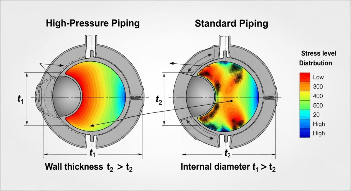
In standard piping design, we use the Barlow equation to calculate wall thickness, which assumes a uniform stress distribution across the pipe wall. However, in high-pressure systems, the ratio of the outer diameter to the inner diameter is highly significant. The stress distribution across a thick-walled cylinder is highly non-linear, with the highest hoop stress occurring at the inner bore.
To account for this, Chapter IX utilizes the Lamé equation for pressure design thickness. The required design thickness, designated as t, is calculated using the outer diameter D and the design pressure P, balanced against the allowable stress S. The formula is expressed as:
Where:
t = Pressure design thickness of the pipe.
D = Outside diameter of the pipe.
P = Internal design gauge pressure.
S = Allowable stress value from Table K-1 of ASME B31.3.
This exponential relationship ensures that as design pressures approach or exceed the allowable stress of the material, the wall thickness scales safely to prevent plastic collapse of the inner fibers.
In my field audits, I frequently catch designers attempting to specify standard ASME B16.9 butt-welding tees or elbows for Chapter IX systems. This is a major compliance failure. Standard fittings are not pre-qualified under Chapter IX. Every single fitting, valve body, and manifold block must either be designed using detailed stress analysis (such as finite element analysis) or qualified through experimental proof testing in accordance with paragraph K304.7.2.
The Role of Autofrettage in High-Pressure Systems
Because the hoop stress is concentrated at the inner bore of a thick-walled pipe, the material near the outer diameter remains underutilized. To optimize the material and dramatically improve fatigue life, we use a process called autofrettage.
During autofrettage, the pipe is subjected to an internal pressure so high that the inner portion of the wall yields plastically, while the outer portion remains elastic. When the pressure is released, the outer elastic zone attempts to contract, placing the inner plastic zone under a permanent state of compressive residual stress. When the pipe is later pressurized in service, this residual compressive stress must first be overcome, significantly reducing the peak tensile stress at the bore and preventing the initiation of fatigue cracks.
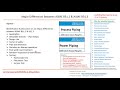
The table below highlights the stark differences in design, material, and testing philosophies between standard ASME B31.3 Normal Fluid Service and Chapter IX High Pressure Piping.
| Design Parameter | Normal Fluid Service (B31.3) | High Pressure Piping (Chapter IX) |
|---|---|---|
| Pressure Limit | Up to ASME B16.5 Class 2500 limits. | Exceeds ASME B16.5 Class 2500 limits. |
| Thickness Formula | Barlow Equation (t = PD / 2SE). | Lamé Equation (t = (D/2)*(1-exp(-P/S))). |
| Allowable Stress Basis | Lower of 1/3 Tensile or 2/3 Yield. | Lower of 1/2 Tensile or 2/3 Yield (Table K-1). |
| Fatigue Analysis | Only required for severe cyclic conditions. | Mandatory fatigue evaluation for all systems. |
| Weld Joint Factor (E) | Ranges from 0.60 to 1.00 based on NDE. | Strictly 1.00 (100% volumetric NDE mandatory). |
| Impact Testing | Governed by curve-based exemptions. | Mandatory for all materials without exception. |
This matrix maps the critical code paragraphs of ASME B31.3 Chapter IX to their physical engineering parameters and field execution requirements.
| Code Paragraph | Technical Entity | Physical Parameter | Field Compliance Rule |
|---|---|---|---|
| K302.3 | Allowable Stress Limits | Yield & Tensile Strength Ratio | Verify Mill Test Reports (MTR) against Table K-1. |
| K304.1 | Straight Pipe Thickness | Inner/Outer Diameter Ratio | Ultrasonic thickness measurement of raw pipe. |
| K311 | Welded Joints | Weld Profile & Reinforcement | Flush grinding of internal and external weld beads. |
| K323.2 | Impact Testing Requirements | Charpy V-Notch Energy (Joules) | Perform sub-size specimen testing at design minimum temp. |
| K344.5 | Ultrasonic Examination | Volumetric Defect Size | 100% UT of all circumferential butt welds. |
Implementing ASME B31.3 Chapter IX Field Inspections
When you are on-site supervising the installation of a Chapter IX piping system, standard mechanical inspection workflows are insufficient. The high energy stored in these compressed fluids means that any installation defect can lead to immediate, violent failure during hydrotesting or commissioning. Use this checklist to verify compliance before signing off on the system.
Field Construction & Quality Control Checklist
-
Material Traceability (Positive Material Identification):
Verify that 100 percent of pipes, flanges, and custom forged blocks have matching Mill Test Reports (MTRs) and have undergone PMI testing to confirm chemical composition. -
Weld Profile Grinding:
Ensure all circumferential butt welds are ground completely flush on both the internal bore (where accessible) and the external surface to eliminate stress concentration points. -
Volumetric Examination (UT/RT):
Confirm that 100 percent of all welds have been examined using Ultrasonic Testing (UT) or Radiographic Testing (RT) in accordance with paragraph K344. -
Thread Profile Inspection:
For high-pressure threaded joints (such as cone-and-thread connections), inspect the threads using liquid penetrant testing to ensure no micro-tears were introduced during machining. -
Hydrostatic Test Pressure Verification:
Verify that the hydrostatic leak test pressure is at least 1.25 times the design pressure, but does not exceed the yield strength of the material at the test temperature.
Field Case Study: Real-World Application
An operating low-density polyethylene (LDPE) plant was experiencing repeated failures at a welded branch connection on a reactor loop operating at 2,800 bar (40,600 psi). The piping had been designed using standard ASME B31.3 Normal Fluid Service rules with heavy-wall pipe. Due to the severe cyclic pressure fluctuations from the reciprocating hyper-compressor, the heat-affected zone of the branch weld developed fatigue cracks, leading to pinhole leaks every six months.
I was brought in to lead the engineering recovery. We completely scrapped the welded branch connection and redesigned the junction using a forged monoblock tee in compliance with ASME B31.3 Chapter IX. The new design utilized XM-19 (Nitronic 50) stainless steel, which was subjected to mandatory Charpy V-notch impact testing at minus 40 degrees. We performed a full fatigue analysis per paragraph K304.8 and applied autofrettage to the forged block.
By replacing the welded joint with a forged, autofrettaged monoblock tee and executing 100 percent ultrasonic examination on the transition welds, we eliminated the stress concentration point. The system has now been operating continuously for over eight years without a single recorded crack or pressure drop. This case proves that trying to bypass Chapter IX rules for high-pressure systems to save on initial fabrication costs is a recipe for operational failure.
Frequently Asked Engineering Questions
At what exact pressure must I use ASME B31.3 Chapter IX?
Why are standard ASME B16.9 fittings prohibited in Chapter IX?
What is autofrettage and why is it used?
Are weld joint quality factors (E) used in Chapter IX?
Can I use standard carbon steel (like A106-B) in Chapter IX?
What are the testing requirements for Chapter IX piping?
===

📚 Recommended Resources: ASME B31.3 Chapter IX
Read these Guides


Related posts:
![Cross-section diagram showing a steel solar pile foundation embedded in layered soil profiles for structural analysis.]()
Essential Geotechnical Pile Design Data for Utility-Scale Solar Structures
![Professional surveyor conducting Topographical Surveys for Solar Projects on a large-scale utility site with complex terrain.]()
Topographical Surveys for Solar Projects: A Technical Engineering Guide
![A geotechnical drill rig performing soil sampling on a large, open field intended for a utility-scale solar farm project.]()
Geotechnical Investigation for Solar Farms: Essential Site Design Guide
![Isometric site plan showing Utility Corridor Planning for Data Centres with color-coded power, water, and telecom infrastructure paths.]()
Utility Corridor Planning for Data Centres: A Strategic Engineering Guide
![Aerial view of a data centre site showcasing perimeter drainage systems, detention basins, and site grading for flood prevention.]()
Drainage Design Considerations for Data Centres: A Technical Guide
![Professional surveyor using a Total Station on a large data centre construction site for topographical mapping.]()
Topographical Surveys for Data Centre Projects: A Technical Guide