Aluminum Extrusion: A Comprehensive Guide for Industrial Engineers
In my 20 years of handling structural piping, custom manifold designs, and heavy industrial frameworks, I have seen many engineers fail because they treated aluminum extrusion as a simple casting process. It is not. It is a highly dynamic thermal-mechanical event where flow stress, billet temperature, and die geometry dictate the structural integrity of your final profile. When you design a custom profile, you are not just drawing a shape; you are controlling the flow of solid metal under immense pressure.
Understanding how the metal behaves as it transitions from a solid billet to a complex hollow profile is the difference between a successful, cost-effective production run and a pile of warped, cracked scrap metal. In this guide, I will share the practical engineering principles, alloy selection criteria, and die design rules that I have used to deliver high-performance structural components across global industrial projects.
Key Engineering Takeaways
- Mastering the extrusion ratio is critical to preventing press stalling and surface defects.
- Alloy selection must balance mechanical strength with extrudability and quench sensitivity.
- Wall thickness uniformity directly prevents profile warping and internal stress concentrations.
How Does the Aluminum Extrusion Process Work?
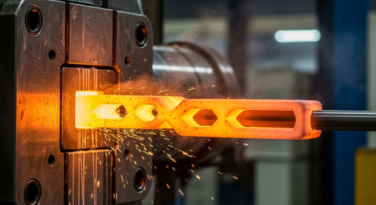
The extrusion process begins with a solid, cylindrical aluminum billet. This billet is preheated in a gas or induction furnace to a temperature range of 400 to 500 degrees Celsius (750 to 930 degrees Fahrenheit). This preheating does not melt the metal; instead, it brings the aluminum past its recrystallization temperature, drastically reducing its yield strength and increasing its ductility.
Once heated, the billet is transferred to the press container. A hydraulic ram forces a dummy block against the billet, pushing it through the die cavity. The die is made of high-strength H13 hot-work tool steel, meticulously heat-treated to withstand extreme thermal shock and mechanical pressures. As the aluminum is squeezed through the die aperture, it assumes the shape of the die profile.
The Mathematics of Extrusion Force
To design profiles safely, we must calculate the required press tonnage. The total extrusion force is a function of the billet cross-sectional area, the flow stress of the alloy at the operating temperature, and the extrusion ratio.
Extrusion Ratio (R) = A_billet / A_profile
Extrusion Force (F) = A_billet * k * ln(R)
Where:
• A_billet is the cross-sectional area of the container liner (square millimeters).
• A_profile is the total cross-sectional area of the extruded shape (square millimeters).
• k is the extrusion constant (deformation resistance) of the specific alloy at a given temperature (Megapascals).
• ln(R) is the natural logarithm of the extrusion ratio.
If your calculated force exceeds 85% of your press capacity, you risk stalling the press or causing premature die failure. In my practice, when dealing with high-strength alloys like 7075, we often have to reduce the billet size or simplify the profile geometry to keep the extrusion ratio within a manageable range of 10:1 to 40:1.
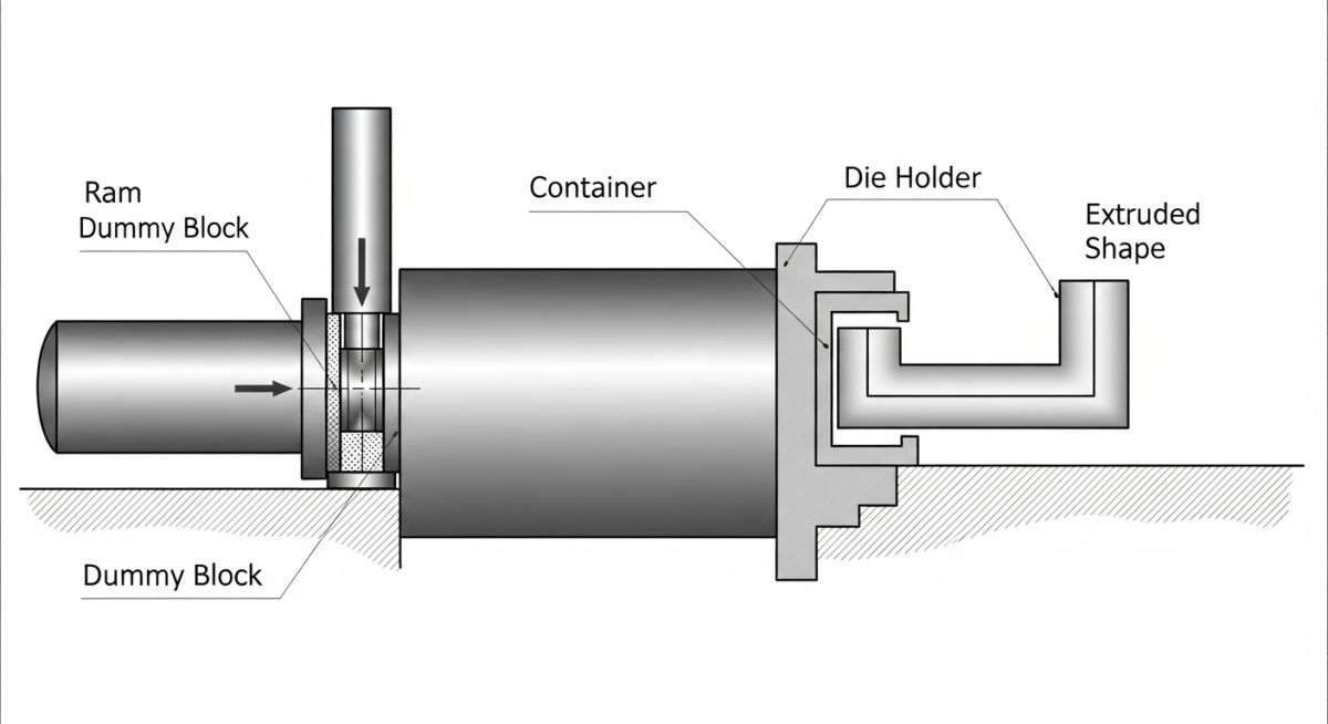
After emerging from the die, the profile travels along the runout table. Here, it must be cooled rapidly to lock in the alloying elements in a solid solution. This step, known as quenching, is performed using air blasts, water sprays, or full water immersion, depending on the alloy’s quench sensitivity. The profile is then stretched mechanically to relieve internal stresses and achieve straightness, followed by cutting and artificial aging in an oven to achieve the desired temper (such as T5 or T6) in accordance with ASTM B221 specifications.
Selecting Alloys for Custom Aluminum Extrusion Profiles
Choosing the correct alloy is the most critical decision in the design phase. 6000-series alloys (magnesium and silicon) are the workhorses of the industry due to their excellent extrudability, moderate strength, and good corrosion resistance. However, for heavy structural or aerospace applications, 7000-series alloys (zinc) or 2000-series alloys (copper) are required, despite being significantly harder to extrude.
| Alloy & Temper | Yield Strength (MPa) | Tensile Strength (MPa) | Extrudability Rating | Primary Applications |
|---|---|---|---|---|
| 6063-T6 | 170 | 215 | Excellent (100%) | Architectural frames, trim, light structural tubing |
| 6061-T6 | 275 | 310 | Good (60%) | Heavy structural frames, marine components, piping |
| 6005A-T6 | 240 | 270 | Very Good (75%) | Railway carriages, structural bus bars, solar racks |
| 7075-T6 | 505 | 570 | Poor (20%) | Aerospace spars, military gear, high-stress tooling |
This matrix maps the core physical parameters and standard references required for high-quality industrial extrusion design.
| Parameter / Entity | Standard Reference | Engineering Function | Design Limit / Rule |
|---|---|---|---|
| Wall Thickness Ratio | Aluminum Association | Prevents differential cooling and warping | Keep adjacent wall thickness ratio below 2:1 |
| Tongue Ratio | ISO 209-1 | Protects die steel from snapping under pressure | Limit tongue ratio to less than 3:1 for hollows |
| Corner Radii | EN 755-9 | Reduces stress concentration and improves flow | Minimum radius of 0.5mm to 1.0mm on all corners |
| Straightness Tolerance | ASTM B221 / EN 12020 | Ensures alignment in structural assemblies | Maximum deviation of 1.5mm per meter of length |
How to Verify Extrusion Profile Tolerances
Before releasing a profile design to the toolmaker, you must run a rigorous geometric check. Minor details on a CAD screen can translate into massive production failures on the press floor. Use this checklist to verify your designs against physical manufacturing realities.
Design Verification Checkpoints
-
Wall Thickness Uniformity: Are adjacent wall thicknesses within a 2:1 ratio? If not, expect material flow imbalances and surface sink marks.
-
Symmetry Check: Is the profile as symmetrical as possible? Symmetrical profiles flow straight out of the die, reducing the need for heavy post-extrusion stretching.
-
Tongue Ratio Validation: For semi-hollow shapes, is the tongue ratio (depth of the cavity divided by the width of the opening) below 3:1? High tongue ratios lead to die breakage.
-
Corner Radii: Have you avoided sharp 90-degree internal corners? A minimum radius of 0.5mm is required to prevent stress cracking in the die and the profile.
-
Alloy-to-Function Match: Is the selected alloy compatible with the required surface finish? For example, use 6063 for high-quality decorative anodizing, not 6061.
Field Case Study: Real-World Application
The Problem: Structural Deflection in Solar Racking
On a utility-scale solar installation in a high-wind coastal region, the structural support frames began showing significant deflection and localized buckling. The original design specified custom extruded profiles made from 6063-T5 aluminum.
The design team had prioritized the high extrudability and smooth surface finish of 6063-T5 to keep costs low. However, they failed to account for the high bending moments caused by wind loads. The yield strength of 6063-T5 (approximately 110 MPa) was completely inadequate, leading to structural deformation under peak wind loads of 140 km/h.
The Outcome: Redesign and Material Upgrade
I was brought in to audit the failure. We immediately halted production and implemented a two-step remediation plan:
- Material Upgrade: We switched the alloy from 6063-T5 to 6061-T6. This increased the yield strength from 110 MPa to 275 MPa, a 150% improvement in load-bearing capacity.
- Profile Optimization: We modified the profile cross-section by increasing the wall thickness of the outer flanges by 1.2mm while reducing the internal web thickness to maintain the same linear weight (kilograms per meter).
The redesigned 6061-T6 profiles successfully passed wind tunnel testing and were deployed across the remaining phases of the project without a single structural failure.
This case highlights why you must never sacrifice mechanical properties for ease of extrusion. Always perform a complete finite element analysis (FEA) of your profile under worst-case loading conditions before finalizing your alloy and temper selection.
Frequently Asked Engineering Questions
What is the difference between direct and indirect extrusion?
Why is wall thickness uniformity so important in profile design?
How does anodizing affect the tolerances of extruded profiles?
What is the purpose of the stretching process after extrusion?
Can 7000-series alloys be easily extruded into complex hollow shapes?
What standards govern the dimensional tolerances of aluminum extrusions?
Complete Course on
Piping Engineering
Check Now
Key Features
- 125+ Hours Content
- 500+ Recorded Lectures
- 20+ Years Exp.
- Lifetime Access
Coverage
- Codes & Standards
- Layouts & Design
- Material Eng.
- Stress Analysis

