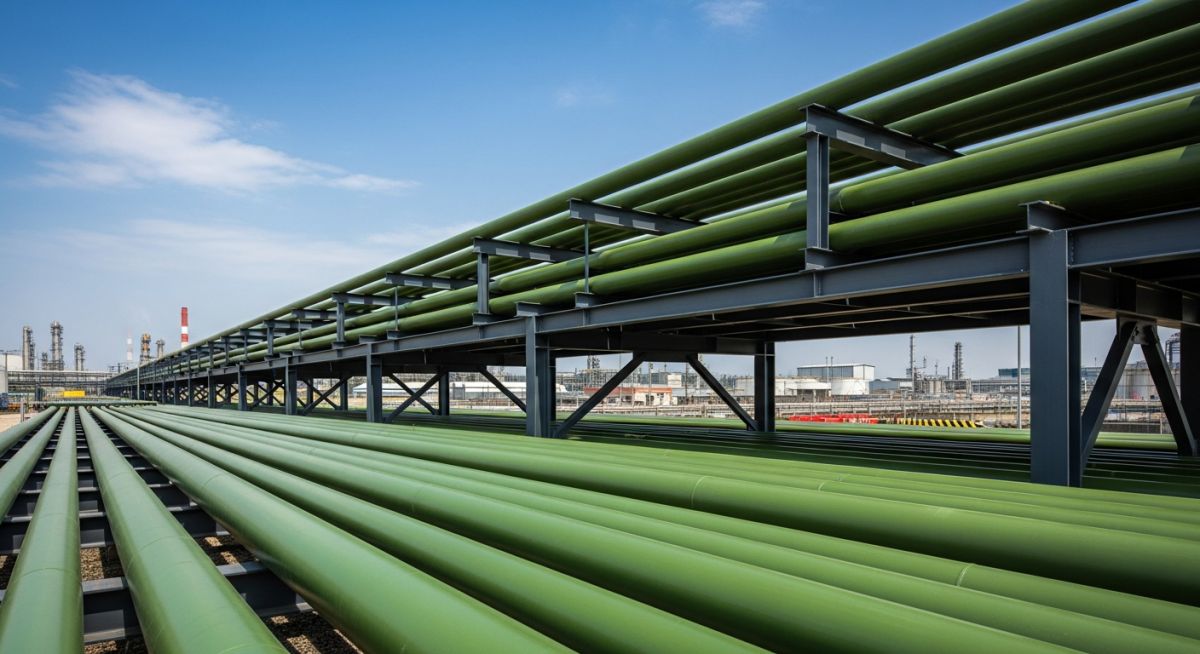
Design and Installation of Aboveground GRE Piping System in Plants
In my 20 years of piping engineering, I have seen many engineers treat Glass Reinforced Epoxy (GRE) like carbon steel. This is a recipe for disaster. GRE is an orthotropic material, meaning its mechanical properties are directionally dependent. When you design an aboveground GRE piping system, you cannot simply copy-paste your metallic piping support spans or jointing methods. You must account for its lower axial modulus, higher thermal expansion, and susceptibility to localized mechanical damage.
Throughout my career on petrochemical and offshore projects, I have managed the transition from traditional alloys to composite systems. While GRE offers unparalleled resistance to corrosive fluids and seawater, its successful implementation aboveground relies entirely on understanding its structural limits. This guide breaks down the core engineering principles, support designs, and installation practices required to ensure a maintenance-free, 30-year operating life.
- Understand the orthotropic nature of GRE and how it affects axial versus hoop stress limits.
- Learn to calculate support spans based on deflection limits rather than structural bending limits alone.
- Master the selection of broad-band, non-abrasive pipe supports to prevent localized wall crushing.
- Implement correct thermal expansion compensation strategies without overloading fragile equipment nozzles.
Why Select an Aboveground GRE Piping System?
When evaluating materials for corrosive environments, such as produced water lines, chemical process lines, or firewater loops, GRE stands out. Unlike carbon steel, it does not require corrosion allowances or expensive external coatings. However, because it is a composite, its mechanical behavior is highly anisotropic. The glass fibers are wound at a specific angle (typically around 55 degrees) to optimize the balance between hoop strength and axial strength. This winding angle makes the pipe twice as strong in the hoop direction as it is in the axial direction.
Designing an Aboveground GRE Piping System Safely
To design a safe aboveground GRE piping system, you must address three primary structural challenges: support span optimization, thermal expansion management, and localized stress concentration.
1. Support Span Calculations
Because the axial modulus of elasticity of GRE is significantly lower than that of steel (typically 10,000 to 20,000 MPa compared to 200,000 MPa for steel), GRE pipes are much more flexible. Consequently, support spans are governed by allowable deflection rather than structural bending stress. The standard allowable deflection for aboveground GRE is limited to 1/300th of the span length, or a maximum of 12.5 mm, to prevent pooling of fluid and excessive bending moments at joints.
The support span length can be calculated using the modified beam deflection formula:
Where:
L = Support span length (mm)
m = Boundary condition factor (typically 22.4 for continuous multi-span configurations)
E = Axial tensile modulus of the GRE pipe (MPa)
I = Moment of inertia of the pipe cross-section (mm^4)
Delta = Allowable mid-span deflection (mm)
w = Uniformly distributed load, including pipe weight, fluid weight, and insulation (N/mm)
2. Thermal Expansion and Stress
The coefficient of thermal expansion for GRE in the axial direction is roughly twice that of carbon steel. However, because its axial modulus is so low, the thermal forces generated on anchors and equipment nozzles are actually much lower (often only 10% to 15% of the force generated by a steel pipe of the same size).
Even so, you must design expansion loops or offsets to absorb this movement, especially in long straight runs. If the system is fully anchored without expansion loops, the compressive stress generated by thermal expansion can cause the pipe to buckle. The compressive stress is calculated as:
Where:
S = Axial thermal stress (MPa)
E = Axial modulus of elasticity (MPa)
alpha = Coefficient of thermal expansion (mm/mm/°C)
dT = Temperature differential between installation and operation (°C)
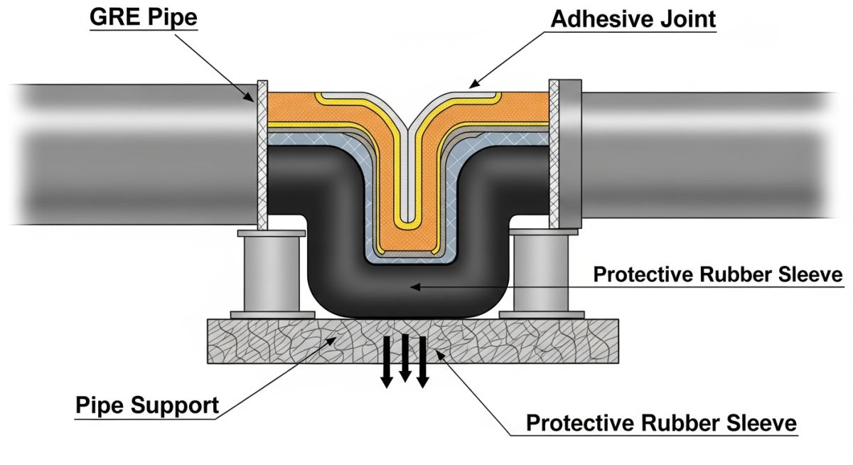
Never use standard, narrow metallic U-bolts directly on bare GRE pipe. The high concentrated loads from tightening these bolts can easily crush the composite wall or cause micro-cracking, leading to premature failure under pressure. Always specify broad-band clamps (minimum 100 mm width) lined with an elastomeric pad (such as neoprene) to distribute the load.
3. Jointing Technologies for Aboveground Service
Selecting the right jointing method is critical for maintaining system integrity. For aboveground systems, the most common joint types are:
- Adhesive Bonded Joints (Taper-Taper): These joints use a two-part epoxy adhesive applied to machined male and female tapered ends. They provide excellent axial strength and are ideal for high-pressure lines, but they require skilled laminators and controlled curing temperatures.
- Flanged Joints: Used primarily for connecting to metallic valves, vessels, or equipment. GRE flanges must be aligned perfectly; uneven bolt torque can easily crack the glass-reinforced flange ring.
- Mechanical Couplings: These allow for axial movement and angular deflection, making them useful for absorbing thermal expansion or ground settlement, though they require external thrust anchors to resist pressure thrust.
To help you compare GRE with traditional piping materials, I have compiled this comparative physical properties table. These values represent typical industry standards but should always be verified with your specific manufacturer’s data sheet.
| Property | GRE (Glass Reinforced Epoxy) | Carbon Steel (ASTM A106 Gr. B) | Engineering Impact |
|---|---|---|---|
| Density (g/cm³) | 1.8 – 2.0 | 7.85 | GRE is 75% lighter, reducing structural steel support loads. |
| Axial Elastic Modulus (GPa) | 10 – 20 | 200 | GRE requires shorter support spans to control deflection. |
| Thermal Expansion (mm/m/°C) | 0.018 – 0.022 | 0.012 | GRE expands more but generates significantly lower anchor forces. |
| Thermal Conductivity (W/m·K) | 0.3 – 0.4 | 45 – 50 | GRE minimizes heat loss and often eliminates the need for insulation. |
This matrix maps the critical components of an aboveground GRE piping system to their governing international standards and design parameters.
| System Component | Governing Standard | Material Specification | Key Design Parameter |
|---|---|---|---|
| Pipes & Fittings | ISO 14692-2 | Epoxy resin with E-glass fibers | Hydrostatic Design Basis (HDB) & wall thickness |
| Adhesive Joints | ISO 14692-4 | Two-part epoxy adhesive kit | Curing temperature profile & joint preparation |
| Flanged Connections | ASME B16.5 / ISO 14692-3 | Flat face GRE flanges | Bolt torque limits & gasket selection (EPDM/PTFE) |
| Pipe Supports | MSS SP-58 / ISO 14692-3 | Carbon steel with elastomer lining | Support width (min 100mm) & contact angle (120-180°) |
How to Verify GRE Field Installations?
In my experience, more than 80% of aboveground GRE failures occur due to poor installation practices. This checklist is designed for field engineers and inspectors to verify that the system is installed correctly before hydrotesting.
-
Laminator Qualification: Verify that all technicians performing adhesive bonding or lamination are certified under ISO 14692-4.
-
Adhesive Storage & Mixing: Ensure epoxy adhesives are stored in temperature-controlled environments (typically 15°C to 30°C) and mixed in exact stoichiometric ratios.
-
Joint Curing: Confirm that heating blankets are used to cure adhesive joints, maintaining the manufacturer-specified temperature (usually 120°C to 150°C) for the required duration.
-
Support Alignment: Check that all pipe supports are aligned perfectly. Misaligned supports introduce severe localized bending stresses that can crack the pipe.
-
Clamping Force: Verify that U-bolts and clamps are fitted with rubber/neoprene pads and are not over-tightened. Clamps must allow axial movement at guide locations.
-
Flange Bolt Torque: Ensure flat-face flanges are bolted using a calibrated torque wrench, following a star pattern in multiple increments up to the maximum specified torque.
Field Case Study: Real-World Application
At a coastal petrochemical facility in the Middle East, a newly installed DN 300 aboveground GRE cooling water line experienced multiple joint failures during commissioning. The line operated at 10 bar and 45°C.
Upon site inspection, I discovered two major design errors. First, the contractor had used standard 50 mm wide steel U-bolts clamped tightly against the bare GRE pipe, causing localized micro-cracking. Second, the system lacked sufficient expansion loops, forcing the thermal expansion to concentrate at the adhesive-bonded elbows, which eventually delaminated.
I led the engineering team to implement a complete remediation plan:
- We replaced all narrow steel U-bolts with 150 mm wide, rubber-lined saddle clamps that allowed the pipe to slide axially.
- We introduced two expansion loops on the long straight runs to safely absorb the 20 mm of calculated thermal expansion.
- We cut out the damaged joints and re-bonded them using qualified laminators, utilizing external heating blankets to ensure a full, uniform cure.
The system was successfully hydrotested at 15 bar (1.5 times the design pressure) with zero leaks. Five years later, this line continues to operate without a single maintenance issue.
Frequently Asked Engineering Questions
What is the maximum operating temperature for an aboveground GRE piping system?
How does UV radiation affect aboveground GRE piping?
Can I use standard steel valves with GRE piping?
Why is water hammer more critical in GRE systems than in steel?
What is the correct way to anchor an aboveground GRE pipe?
How do you perform a hydrotest on an aboveground GRE line?
Complete Course on
Piping Engineering
Check Now
Key Features
- 125+ Hours Content
- 500+ Recorded Lectures
- 20+ Years Exp.
- Lifetime Access
Coverage
- Codes & Standards
- Layouts & Design
- Material Eng.
- Stress Analysis