How Buried Pipeline Stress Analysis Coating Factor Impacts Piping Integrity
In my 20+ years of designing high-pressure transmission lines, I have seen many engineers treat soil-pipe interaction as a secondary calculation. They plug in default soil properties and completely ignore how the external coating alters friction. When you transition from a rough concrete weight coating to a slick three-layer polyethylene (3LPE) system, the axial resistance drops dramatically. If your stress model does not account for this shift, your calculated expansion at critical tie-ins and elbows will be dangerously underestimated, leading to localized overstress or catastrophic upheaval buckling.
Key Engineering Takeaways
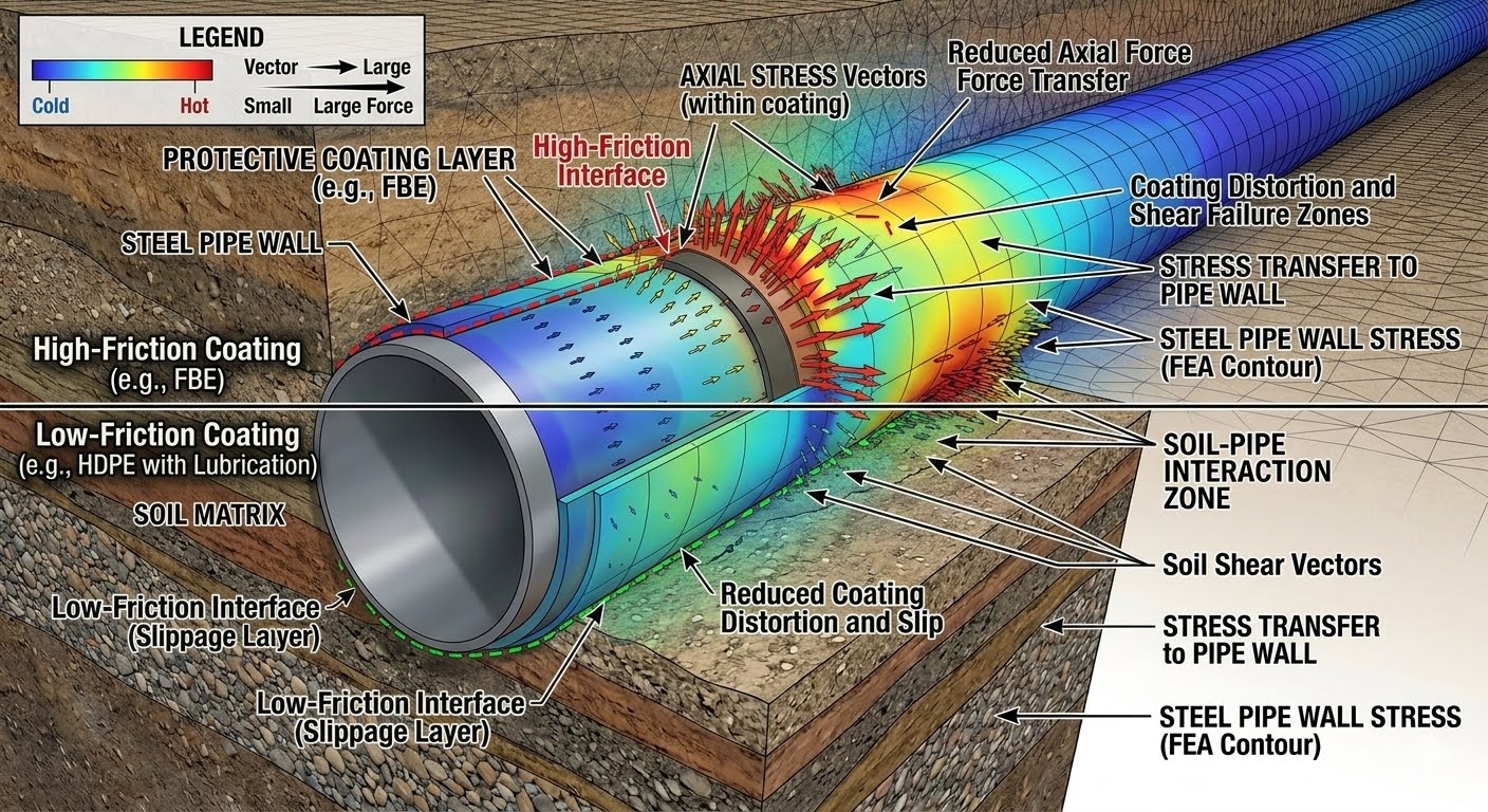
- Friction Reduction: Modern slick coatings like 3LPE and 3LPP can reduce soil-pipe friction by up to 50% compared to bare steel, significantly increasing thermal expansion displacements.
- Virtual Anchor Length: A lower coating factor extends the virtual anchor length, forcing larger volumes of pipe to move and transfer load to unconstrained bends.
- Code Compliance: Accurate modeling of the coating factor is required to satisfy stress limits defined in ASME B31.4 and ASME B31.8.
Complete Course on
Piping Engineering
Check Now
Key Features
- 125+ Hours Content
- 500+ Recorded Lectures
- 20+ Years Exp.
- Lifetime Access
Coverage
- Codes & Standards
- Layouts & Design
- Material Eng.
- Stress Analysis
Why Buried Pipeline Stress Analysis Coating Factor Matters
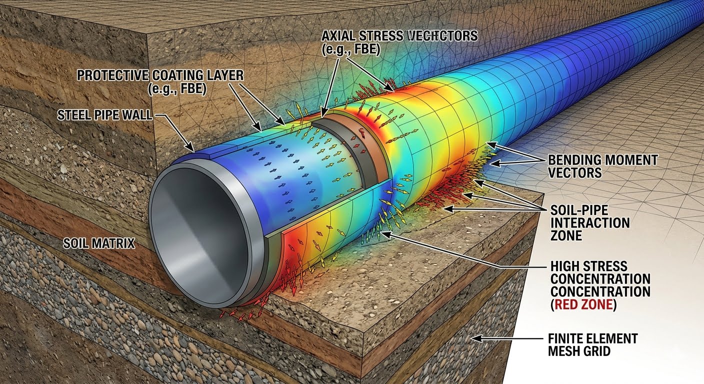
Soil-Pipe Friction Scaling: The coating factor acts as a multiplier on the soil internal friction angle to determine the interface shear strength between the pipeline and the backfill. This adjustment ensures that stress models accurately reflect real-world axial restraint variations across different coating materials.
When a pipeline is buried, the surrounding soil acts as a continuous, non-linear spring restraining its movement. This interaction is modeled using bilinear or elastoplastic soil springs in the axial, transverse, vertical uplift, and vertical bearing directions, as standardized by the American Society of Civil Engineers (ASCE) and the American Lifelines Alliance (ALA).
The axial soil spring is highly dependent on the interface friction angle between the pipe surface and the soil. This interface friction angle, typically denoted as delta, is calculated using the soil’s internal friction angle, phi, and the coating factor, fc:
The ultimate axial soil resistance per unit length, Tu, is then calculated using the following governing equation:
Where:
– D = Outside diameter of the pipeline
– H = Depth of soil cover to the pipe centerline
– gamma = Effective unit weight of the soil backfill
– K0 = Coefficient of earth pressure at rest
– delta = Interface friction angle (fc * phi)
The Mathematical Impact on Virtual Anchor Length
The virtual anchor length, Lv, is the distance from a free end or bend over which the axial friction force fully restrains the thermal and pressure expansion of the pipeline. It is expressed as:
Where:
– A = Cross-sectional area of the steel pipe
– E = Modulus of elasticity of steel
– alpha = Coefficient of thermal expansion
– dT = Design temperature differential
Let us look at a practical design scenario. Consider a 24-inch (0.6096 m) gas pipeline buried in sand with an internal friction angle of 30 degrees, a cover depth of 1.2 meters, and a soil unit weight of 18 kN/m³. The earth pressure coefficient at rest is 0.5.
If we assume a rough coating like Concrete Weight Coating with a coating factor of 1.0, the interface friction angle is 30 degrees. The calculated ultimate axial soil resistance, Tu, is approximately 17.91 kN/m.
If we switch the design to a slick 3LPE coating with a coating factor of 0.5, the interface friction angle drops to 15 degrees. The resulting Tu is only 8.32 kN/m. This represents a 53% reduction in axial restraint. Consequently, the virtual anchor length, Lv, more than doubles. The pipeline will push twice as far into adjacent elbows, significantly increasing the bending stresses at those fittings.
Standard Coating Factors for Stress Analysis
Coating Friction Coefficients: These standardized design values represent the ratio of pipe-soil interface friction to the internal friction of the surrounding soil matrix. Selecting the correct factor prevents under-designing expansion loops and over-designing anchor blocks.
The table below outlines the typical coating factors used in industry-standard stress analysis software, based on extensive experimental testing and field measurements.
| Coating Type | Coating Factor (fc) | Friction Behavior | Stress Analysis Impact | Reference Standard |
|---|---|---|---|---|
| Bare Steel | 0.90 – 1.00 | High Friction | Short virtual anchor length; high axial stress | ASCE Guidelines |
| Fusion Bonded Epoxy (FBE) | 0.70 – 0.80 | Moderate Friction | Standard baseline for modern onshore lines | ISO 21809-1 |
| 3-Layer Polyethylene (3LPE) | 0.50 – 0.60 | Very Low Friction | Long virtual anchor length; high bend displacement | ISO 21809-1 |
| 3-Layer Polypropylene (3LPP) | 0.50 – 0.55 | Extremely Low Friction | Critical for high-temperature deepwater lines | ISO 21809-1 |
| Coal Tar Enamel | 0.90 – 1.00 | High Friction | Legacy systems; high soil bonding | AWWA C203 |
| Concrete Weight Coating (CWC) | 1.00 – 1.20 | Very High Friction | Minimal expansion; high local shear transfer | ISO 21809-5 |
Technical Mapping & Specifications Matrix
To ensure seamless integration between geotechnical reports and stress analysis software, use the following mapping matrix to align physical parameters with software inputs.
| Parameter / Entity | Acronym | Physical Unit | Governing Standard | Stress Model Role |
|---|---|---|---|---|
| Ultimate Axial Soil Resistance | Tu | N/mm or lb/in | ALA Guidelines | Defines the limit of the elastoplastic axial spring |
| Soil Internal Friction Angle | phi | Degrees | ASTM D3080 | Base geotechnical input for shear strength |
| Virtual Anchor Length | Lv | Meters or Feet | ASME B31.8 Appendix G | Determines the active expansion zone of the line |
| Coating Factor | fc | Dimensionless | API RP 1111 | Scales the soil-pipe interface friction |
Verifying Buried Pipeline Stress Analysis Coating Factor
Design Verification Protocol: This quality assurance checklist ensures that the coating factor used in stress software matches the actual procurement specifications and geotechnical reports. Verifying these inputs prevents structural failures at pipeline transitions and bends.
During the design review phase, I always perform a rigorous check of the soil-pipe interaction parameters. The checklist below represents the exact steps my team follows to validate the coating factor inputs before finalizing any stress analysis report.
Engineering Verification Checklist
-
Geotechnical Report Alignment: Verify that the soil internal friction angle (phi) used in the stress model matches the lower-bound values specified in the project-specific geotechnical report.
-
Coating Specification Match: Cross-reference the coating factor (fc) with the actual pipeline coating data sheet (e.g., 3LPE, FBE, or concrete weight coating) to ensure the correct multiplier is applied.
-
Software Input Validation: Confirm that the axial soil spring multiplier in CAESAR II or AutoPIPE is explicitly set to the correct coating factor, rather than defaulting to 1.0.
-
Transition Zone Modeling: Ensure that the transition from buried to aboveground piping is modeled with a realistic soil-pipe friction profile, accounting for any local soil compaction variations.
-
Upheaval Buckling Sensitivity: For high-temperature lines, run a sensitivity analysis with both upper-bound and lower-bound coating factors to evaluate the risk of upheaval buckling.
Field Case Study: Real-World Application
Pipeline Expansion Failure Analysis: This field investigation highlights the consequences of using an incorrect coating factor during the design phase of a high-temperature hydrocarbon pipeline. Correcting the friction model resolved unexpected displacement issues at an aboveground scraper receiver station.
The Problem: Unexpected Station Displacement
During the commissioning of a 24-inch crude oil pipeline coated with 3LPE, the operator observed massive, unexpected axial displacements at the scraper receiver station. The pipeline was operating at 75 degrees Celsius. The design team had modeled the system using a default coating factor of 1.0, assuming standard bare steel friction.
As a result, the actual displacement at the station tie-in reached 165 mm, which was more than double the predicted design value of 70 mm. This excessive movement overloaded the anchor block, causing structural deformation of the piping supports and threatening the integrity of the flange connections.
The Outcome: Corrective Modeling & Mitigation
I was brought in to perform a forensic stress analysis. I immediately identified that the 3LPE coating had a true coating factor of 0.5, which had not been accounted for in the original model. Re-running the simulation with the correct coating factor of 0.5 revealed that the virtual anchor length was actually 420 meters instead of the originally calculated 200 meters.
To resolve the issue without re-burying the entire line, we installed a series of expansion offsets upstream of the station and reinforced the anchor block to handle the higher thermal loads. This modification safely absorbed the expansion and brought the system back into full compliance with ASME B31.4.
This case study proves that the coating factor is not just a theoretical variable. It has massive, real-world consequences on the physical behavior of your piping system. Always design with the actual coating properties in mind.
Frequently Asked Engineering Questions
Pipeline Stress FAQ: This technical reference addresses common queries regarding soil-pipe interaction, software modeling techniques, and code compliance for buried pipeline stress analysis.
How does the coating factor affect virtual anchor length?
What is the difference in coating factors between FBE and 3LPE?
Which design codes govern the selection of pipeline coating factors?
How do you model varying coating factors in CAESAR II?
Can a high coating factor lead to upheaval buckling?
How does soil moisture content influence the effective coating factor?
===
