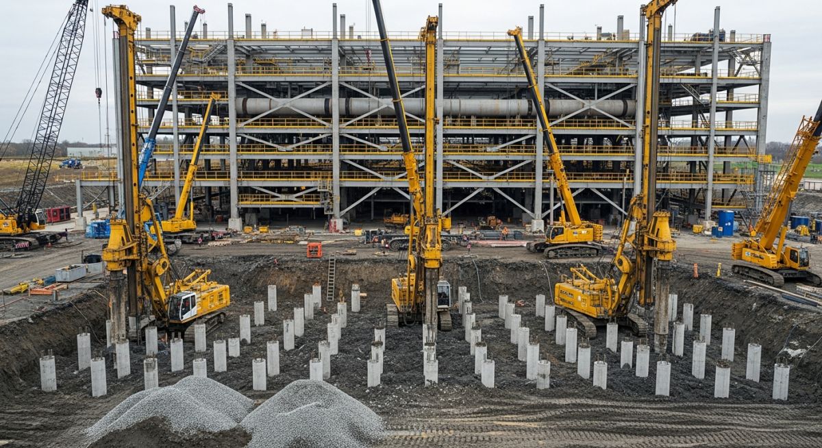
Overview of Pile Foundation Design for Industrial Piping Infrastructure
In my two decades of experience managing complex piping projects, I have learned that the foundation is the silent partner of every successful plant. When we deal with heavy-duty process piping, particularly in areas with high water tables or soft alluvial deposits, shallow footings simply do not suffice. We must rely on deep foundations to mitigate settlement risks that could otherwise lead to catastrophic flange leaks or pipe stress failures.
This guide explores the technical rigor required to design pile foundations that maintain structural integrity under extreme thermal expansion and vibration loads. We will examine the transition from geotechnical reports to final pile cap reinforcement, ensuring your piping systems remain aligned and operational for their entire design life.
Key Takeaways for Engineers
- Understand the critical role of skin friction versus end-bearing capacity.
- Learn to calculate lateral load resistance for pipe rack bents.
- Master the integration of geotechnical data into structural pile modeling.
- Identify common failure modes in pile-to-cap connections.
Technical Deep-Dive: Pile Foundation Design Principles
Pile Foundation Design: The analytical determination of pile capacity based on soil shear strength parameters, pile geometry, and installation methods, governed by AISC and ASCE design codes.
Designing a pile foundation begins with the geotechnical investigation report. I always emphasize that the allowable axial capacity of a pile is the sum of the shaft resistance (skin friction) and the base resistance (end bearing). We calculate the ultimate capacity using the formula Q_ult = Q_s + Q_b, where Q_s represents the integration of side shear along the pile length and Q_b is the product of the base area and the soil bearing capacity at the pile tip.
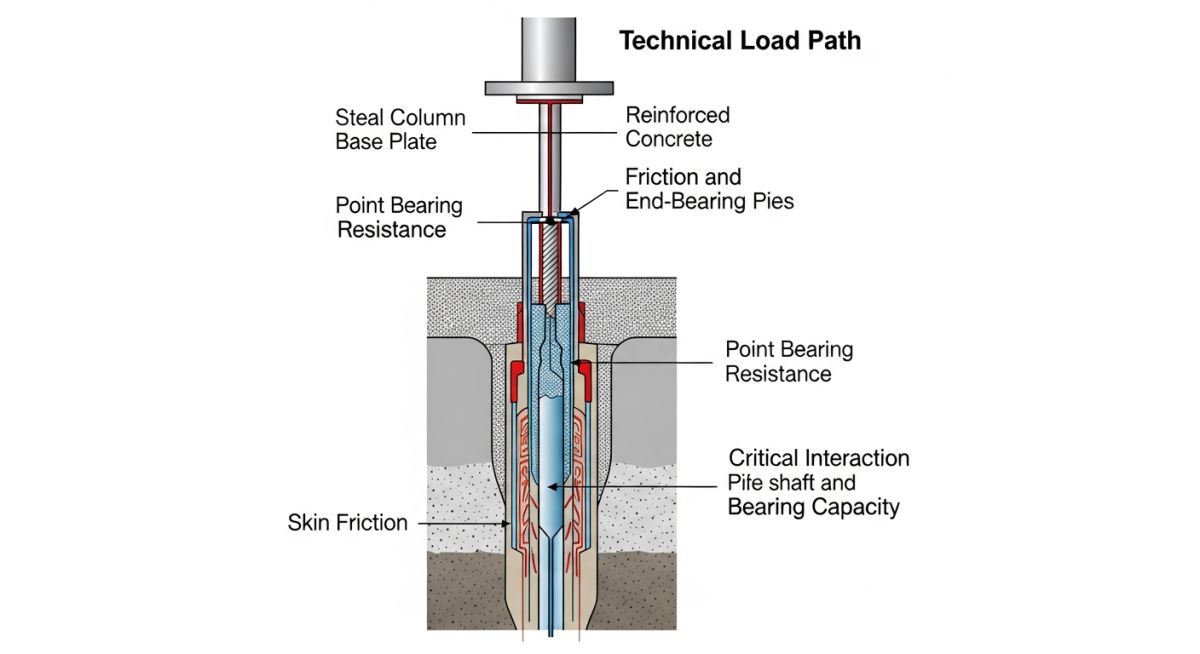
For industrial piping, lateral loads are often more critical than vertical loads due to thermal expansion forces. We model these using the p-y curve method, which accounts for the non-linear soil-structure interaction. When a pipe rack exerts a horizontal force, the pile acts as a beam on an elastic foundation. We must ensure the bending moment at the pile-to-cap connection does not exceed the structural capacity of the reinforced concrete section.
Field Warning: Negative Skin Friction
In sites with consolidating soils or recent fill, be aware of downdrag forces. If the soil settles around the pile, it exerts a downward force that reduces the effective capacity. Always subtract this downdrag from your allowable load calculations to prevent unexpected settlement.
When specifying pile types, I categorize them into displacement piles (driven) and non-displacement piles (bored/drilled). Driven piles are excellent for densifying granular soils, but they introduce vibration risks near existing sensitive process equipment. Bored piles, or drilled shafts, allow for visual inspection of the bearing strata but require careful slurry management to prevent borehole collapse.
Finally, the pile cap design must follow ACI 318 requirements for deep members. We treat the pile cap as a rigid block, ensuring the punching shear capacity is checked at the critical section, typically located at a distance d/2 from the face of the column or pedestal. Proper reinforcement detailing at the pile-to-cap interface is non-negotiable for seismic resilience.
Foundation Selection Trade-offs: A comparative analysis of deep foundation systems versus shallow alternatives, focusing on long-term settlement control and structural reliability in industrial environments.
Advantages
- Superior settlement control for heavy, vibration-sensitive equipment.
- Effective load transfer through liquefiable or highly compressible soil layers.
- High lateral load resistance for tall pipe racks and wind-loaded structures.
- Ability to reach competent strata in sites with deep overburden.
- Reduced footprint compared to large, spread-footing mats.
Disadvantages
- Significantly higher mobilization and installation costs.
- Complex site logistics for heavy piling rigs and material storage.
- Risk of pile damage during driving in rocky or obstructed ground.
- Potential for noise and vibration complaints in urban or brownfield sites.
- Requirement for specialized geotechnical testing (e.g., PDA or CSL).
Industrial Infrastructure Deployment: Strategic implementation of deep foundation systems across diverse process plant environments to ensure operational stability and structural safety.
High-Pressure Steam Distribution Racks
In large-scale refineries, steam lines generate significant thermal thrust forces that require robust lateral restraint. Pile foundations provide the necessary stiffness to prevent rack swaying, ensuring that expansion loops function within their design parameters without overstressing the piping connections.
Cryogenic Storage Tank Foundations
Cryogenic tanks require precise leveling to maintain internal pressure integrity and prevent uneven stress distribution. Deep piles are used to bypass soft surface soils, ensuring that the tank base remains stable even during seasonal groundwater fluctuations that could cause differential settlement.
Offshore Platform Piping Risers
For marine-based industrial facilities, piles are the primary method for anchoring structures to the seabed. These foundations must resist extreme cyclic lateral loads from wave action and currents, requiring high-strength steel pipe piles driven deep into the marine sediment.
Compressor Station Vibration Mitigation
Reciprocating compressors generate dynamic loads that can propagate through the soil and damage nearby infrastructure. Deep pile foundations are designed to isolate these vibrations by anchoring the compressor skid to a stiff, deep-seated concrete block, effectively decoupling the equipment from the surrounding soil.
In my two decades of field experience, the accuracy of pile foundation design hinges entirely on the precision of the input load parameters. We must categorize these loads into vertical, lateral, and moment components to ensure the structural integrity of the pipe rack or equipment support. The following table outlines the critical design variables that every engineer must verify against ASCE 7 standards before finalizing the pile schedule.
When evaluating these parameters, consider the interaction between the pile cap and the soil medium. The effective load capacity is not merely a function of the pile material strength but is heavily influenced by the skin friction and end-bearing resistance provided by the surrounding strata. Always ensure that the factor of safety applied to these loads aligns with the specific geotechnical report provided for the project site.
| Load Type | Design Standard | Primary Consideration |
|---|---|---|
| Axial Compression | ASTM D1143 | End bearing vs skin friction distribution |
| Lateral Shear | API RP 2A | Soil modulus and pile stiffness (EI) |
| Uplift/Tension | ASCE 20 | Effective overburden pressure and pile weight |
Engineers should note that lateral loads often govern the design of slender piles in soft clay environments. By cross-referencing these values with the AISC steel design codes, we can optimize the pile section to prevent buckling while maintaining the required serviceability limits for piping alignment.
The following matrix serves as a technical roadmap for mapping structural entities to their respective governing codes and physical performance metrics. In my practice, I have found that maintaining this level of documentation is vital for audit trails and long-term asset management in high-pressure industrial environments.
Each entity listed below represents a critical node in the soil-structure interaction model. By standardizing these definitions, we reduce the risk of miscommunication between the geotechnical consultants and the structural design team, ensuring that the pile foundation design remains robust throughout the project lifecycle.
| Entity | Acronym | Standard Reference |
|---|---|---|
| Pile Load Test | PLT | ASTM D1143 |
| Lateral Load Capacity | LLC | API RP 2A |
| Soil Modulus | Ks | ASCE 7 |
This matrix should be updated as site-specific data becomes available during the piling installation phase. Discrepancies between the design model and the actual pile driving logs must be addressed immediately to verify that the design assumptions remain valid.
Verification of pile foundation design in the field is not a passive activity; it requires active engagement with the installation process. Based on my experience, the following checklist ensures that the theoretical design translates into a stable physical asset. Use this to validate site conditions against the original geotechnical report.
-
01.
Verify the actual soil strata encountered during drilling matches the borehole logs provided in the ASCE geotechnical report. -
02.
Confirm the pile driving hammer energy and blow counts are within the calculated range for the required bearing capacity. -
03.
Check for pile verticality and alignment tolerances as specified in API standards to prevent eccentric loading. -
04.
Inspect the pile head condition post-driving to ensure no structural damage or concrete spalling occurred during the installation process. -
05.
Validate the pile cap reinforcement layout against the structural drawings, ensuring proper concrete cover and bar spacing.
If any of these checkpoints fail, you must halt construction and perform a re-evaluation of the pile capacity. In my experience, catching a deviation in pile depth or alignment early saves significant costs compared to remedial measures required after the pile cap is poured. Always maintain a detailed log of these verifications for the project quality assurance file.
The Problem: Unexpected Settlement in Soft Clay
During the construction of a major petrochemical pipe rack, we encountered significant settlement issues that threatened the alignment of the process lines.
- Inaccurate soil modulus assumptions in the initial geotechnical report.
- Excessive lateral deflection under wind load conditions for the tall pipe rack.
- Inadequate pile depth to reach the competent bearing stratum.
- High water table causing liquefaction-like behavior in the upper soil layers.
The Outcome: Successful Remediation and Stabilization
We implemented a comprehensive redesign that restored the structural integrity of the foundation system.
- Increased pile length by 15% to reach the deeper dense sand layer.
- Installed additional batter piles to resist lateral wind forces.
- Implemented a rigorous pile load testing program to verify the new capacity.
- Achieved a 40% reduction in settlement within the first six months of operation.
My recommendation for similar projects is to always perform a pilot pile test if the site conditions show any variability. Relying solely on theoretical models without empirical site verification is a high-risk strategy that often leads to the exact type of settlement issues we faced here.
How do I determine the required pile length?
Determining pile length requires a synthesis of geotechnical data and structural load requirements. You must follow these steps:
- Analyze the borehole logs to identify the depth of the competent bearing stratum.
- Calculate the required skin friction and end-bearing capacity based on ASCE standards.
- Perform a wave equation analysis to estimate the driving resistance.
- Adjust the length based on the factor of safety required for the specific industrial application.
What is the role of lateral load analysis?
Lateral load analysis is critical for structures subjected to wind, seismic, or thermal expansion forces. In my experience, this is often the governing factor for pile design in soft soils.
- It prevents excessive pile head deflection that could damage piping connections.
- It ensures the pile section has sufficient bending stiffness (EI) to resist buckling.
- It utilizes the p-y curve method to model soil-structure interaction as per API RP 2A.
When should I use batter piles?
Batter piles are inclined piles used to resist significant horizontal loads that vertical piles cannot handle alone. I recommend them when:
- The lateral load exceeds the capacity of the vertical pile group.
- The structure is subject to high seismic activity requiring increased stiffness.
- Space constraints prevent the use of a larger pile cap to distribute lateral forces.
How does soil liquefaction affect design?
Liquefaction causes a temporary loss of soil shear strength, which can lead to catastrophic foundation failure. To mitigate this:
- Extend piles through the liquefiable layer into stable, non-liquefiable soil.
- Design the pile to resist buckling due to the loss of lateral soil support.
- Consult ASCE 7 seismic provisions for specific site-class requirements.
What is the importance of pile load testing?
Pile load testing is the only way to empirically verify the design capacity. It serves as the final validation of the geotechnical model.
- It confirms the skin friction and end-bearing values assumed in the design.
- It identifies potential installation issues that could compromise capacity.
- It provides the necessary data to optimize the pile count, potentially saving significant project costs.
How do I manage pile group effects?
Pile group effects occur when the stress zones of individual piles overlap, reducing the overall efficiency of the group. To manage this:
- Increase pile spacing to at least three times the pile diameter.
- Apply efficiency factors to the total capacity calculation as per standard geotechnical practice.
- Consider the settlement of the entire group, which is often greater than that of a single pile.
📚 Recommended Resources: Pile Foundation Design
Read these Guides
- 📄 Ground Improvement Techniques for Renewable Energy Projects: Engineering Design Guide
- 📄 Essential Foundation Requirements for BESS Containers: A Technical Design Guide
- 📄 Strategic Site Selection Criteria for BESS Facilities Engineering Design
- 📄 Essential Foundation Design Inputs for Hydrogen Plant Geotechnical Reports
Complete Course on
Piping Engineering
Check Now
Key Features
- 125+ Hours Content
- 500+ Recorded Lectures
- 20+ Years Exp.
- Lifetime Access
Coverage
- Codes & Standards
- Layouts & Design
- Material Eng.
- Stress Analysis
