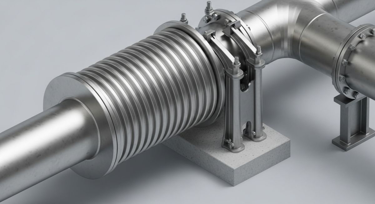
Design Considerations for a Piping System with an Expansion Bellow
In my two decades of field experience, I have seen too many piping failures caused by the improper application of expansion bellows. These components are not “magic bullets” for poor layout design; they are precision-engineered pressure vessels that demand rigorous attention to anchor loads, pressure thrust, and cycle life. When you introduce a bellow into a system, you are essentially creating a localized point of high flexibility in an otherwise rigid structure, which shifts the entire stress profile of your piping run.
Designing a piping system with an expansion bellow requires a disciplined approach to calculating the resultant forces that act on your supports. If you fail to account for the pressure thrust—the force generated by internal pressure acting on the effective area of the bellows—your anchors will likely fail, leading to catastrophic system rupture. This guide breaks down the technical requirements for safe, code-compliant integration.
Key Takeaways for Piping Engineers:
- Always calculate the pressure thrust force using the effective area of the bellows.
- Ensure main anchors are designed to withstand the full pressure thrust plus spring rates.
- Verify the cycle life requirements against the expected thermal transients.
- Strictly adhere to EJMA standards for bellows movement and installation alignment.
Technical Design Considerations for a Piping System with an Expansion Bellow
Expansion Bellow Stress Analysis: The analytical process of evaluating the interaction between thermal displacement, internal pressure, and the mechanical stiffness of the bellows assembly to ensure structural stability under operational conditions.
When I evaluate a piping system with an expansion bellow, my first step is always the calculation of the pressure thrust force. This force is often underestimated by junior engineers. The pressure thrust is defined as the product of the internal design pressure and the effective area of the bellows. Unlike a rigid pipe, the bellows acts like a piston; if the system is not properly anchored, the pressure will attempt to extend the bellows to its full length, potentially causing a blowout.
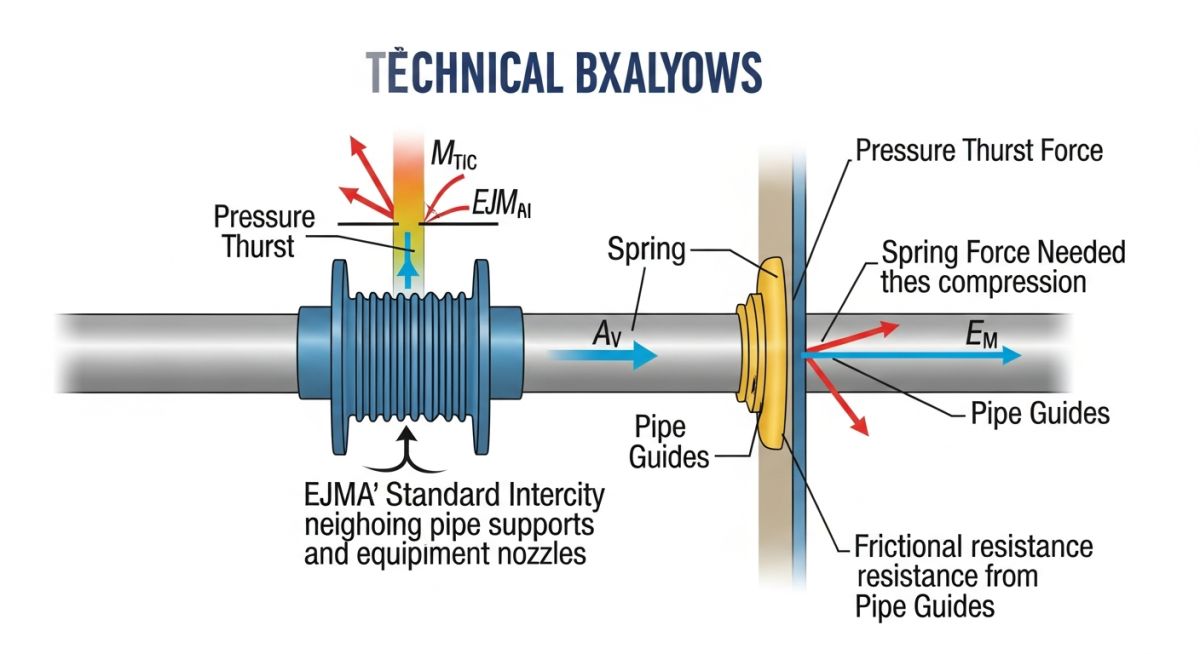
The formula for pressure thrust is F = P times A, where P is the internal pressure and A is the effective area of the bellows. You must design your main anchors to resist this force, which is significantly higher than the force required to compress or extend the bellows based on its spring rate. In my experience, the most common failure mode is the use of intermediate guides that are too weak to prevent the bellows from buckling under this thrust.
Critical Field Warning: Anchor Rigidity
Never rely on standard pipe supports to act as main anchors for an expansion bellow. A main anchor must be designed to withstand the full pressure thrust, the force required to deflect the bellows, and the frictional forces of the pipe guides. If your anchor is not infinitely rigid relative to the bellows, the resulting movement will cause premature fatigue failure of the bellows convolutions.
Beyond pressure thrust, you must account for the spring rate of the bellows. The total force on the anchor is the sum of the pressure thrust and the force required to move the bellows (spring rate times displacement). I always reference the EJMA (Expansion Joint Manufacturers Association) standards, which provide the definitive methodology for calculating these values. When performing your stress analysis in software like CAESAR II, ensure you are using the correct stiffness values provided by the manufacturer, as these vary significantly based on the number of plies and the material of construction.
Bellows Integration Trade-offs: A technical assessment of the operational benefits versus the structural and maintenance complexities introduced by flexible piping elements.
Advantages
- Compact design footprint compared to large expansion loops.
- Superior vibration isolation for rotating equipment connections.
- Effective compensation for multi-axial movements in tight spaces.
- Reduced total piping weight by eliminating massive loop structures.
- Lower pressure drop compared to complex piping configurations.
Disadvantages
- High maintenance requirements and limited service life.
- Risk of catastrophic failure if anchors are improperly designed.
- Sensitivity to particulate accumulation in the bellows convolutions.
- Requirement for specialized, high-cost installation and alignment.
- Susceptibility to flow-induced vibration and resonance issues.
Industrial Bellows Deployment: Strategic implementation of expansion joints across high-temperature and high-vibration process environments to ensure system longevity.
Turbine Exhaust Ducting
In power generation, turbine exhaust lines experience extreme thermal transients during startup and shutdown. Metallic bellows are essential here to absorb the rapid axial expansion of large-diameter ducting, preventing the transfer of massive thermal loads to the turbine casing.
Cryogenic Process Piping
In LNG facilities, piping systems undergo extreme contraction during cool-down. Expansion bellows designed for cryogenic service allow for the necessary contraction while maintaining a vacuum-tight seal, protecting the integrity of the insulation jacket and the inner process pipe.
Pump Suction and Discharge
Pumps generate high-frequency vibrations that can lead to fatigue in rigid piping connections. Installing bellows at the pump nozzle isolates the piping system from these vibrations, significantly extending the mean time between failures for both the pump seals and the piping welds.
Refinery Heat Exchanger Nozzles
Heat exchangers often experience differential thermal expansion between the shell and the tube bundle. Bellows integrated into the shell side allow for this differential movement, preventing the overstressing of the nozzle connections and the potential for hazardous process leaks.
When designing a piping system with an expansion bellow, engineers must reconcile the bellows’ inherent flexibility with the rigid requirements of the surrounding piping network. The following table outlines critical performance parameters that dictate the selection of bellows based on EJMA standards. These values are not merely suggestions but represent the operational boundaries within which the bellows can safely absorb thermal growth without risking premature fatigue failure or pressure boundary rupture.
It is imperative to note that these parameters are interdependent; for instance, increasing the operating pressure significantly reduces the allowable axial movement capacity of a standard multi-ply bellows. Designers must verify these metrics against the specific ASME B31.3 process conditions to ensure that the pressure-thrust forces do not exceed the structural capacity of the adjacent pipe supports or anchors.
| Parameter | Standard/Metric | Design Consideration |
|---|---|---|
| Axial Spring Rate | N/mm (lb/in) | Determines anchor load requirements |
| Cycle Life | EJMA Fatigue Curve | Must exceed project design life |
| Effective Area | Square Millimeters | Used to calculate pressure thrust |
| Lateral Offset | Millimeters | Requires multi-ply or gimbal design |
Always confirm that the bellows manufacturer provides a certified test report validating these parameters under the specific temperature and pressure cycles expected during the plant’s operational life.
The integration of expansion bellows into complex process piping requires a rigorous mapping of mechanical entities to their respective regulatory frameworks. This matrix serves as a technical bridge, ensuring that every component—from the bellows element itself to the supporting structural steel—is accounted for in the stress analysis model.
By aligning these entities with their governing codes, we minimize the risk of design oversights that often lead to field failures. Whether dealing with high-pressure steam lines or cryogenic transfer systems, the following mapping ensures that the interaction between the bellows’ flexibility and the system’s rigidity is correctly captured in software like CAESAR II or AutoPIPE.
| Entity | Governing Standard | Key Parameter |
|---|---|---|
| Expansion Bellows | EJMA | Pressure Thrust Force |
| Piping System | ASME B31.3 | Thermal Expansion Stress |
| Pipe Anchors | AISC 360 | Reaction Force/Moment |
| Flange Connections | ASME B16.5 | Bolt Load Capacity |
Engineers should utilize this matrix during the P&ID and isometric review phases to verify that all necessary support types are specified and that the piping flexibility analysis reflects the actual hardware installed on-site.
Piping system with an expansion bellow installations are notoriously sensitive to site-level errors. Even a perfectly engineered design can fail if the installation team ignores the fundamental requirements for alignment, support, and protection. This checklist provides a systematic approach to verifying the integrity of the installation before the system is pressurized or commissioned.
- Alignment Verification: Ensure the bellows is not being used to correct piping misalignment. The bellows must be installed in a stress-free state, with the pipe ends perfectly aligned to the bellows flanges.
- Anchor Integrity: Verify that all main anchors are fully welded and inspected per AWS D1.1. The anchors must be capable of resisting the full pressure thrust force, which is often significantly higher than the thermal expansion forces.
- Shipping Bar Removal: Confirm that all shipping bars or locking devices have been removed after the piping is fully supported. Leaving these in place renders the bellows rigid and will lead to immediate failure during thermal startup.
- Flow Direction: Check the flow arrow on the bellows sleeve. Installing a bellows with an internal liner in the wrong direction can lead to flow-induced vibration and catastrophic liner collapse.
- Support Proximity: Verify that the first pipe guide is located within the distance specified by the manufacturer (typically 4 pipe diameters) to prevent buckling of the bellows element.
- Protection from Debris: Ensure the bellows is protected from weld spatter, grinding dust, and insulation materials that could restrict the movement of the convolutions.
By strictly adhering to these verification steps, you ensure that the design intent is preserved in the field. Always document the final “as-installed” condition, including the cold-set position of the bellows, to provide a baseline for future maintenance inspections and fatigue life monitoring.
Field Case Study: Real-World Application
The Problem: Premature Bellows Failure in Steam Header
A high-pressure steam header experienced repeated bellows failure within six months of commissioning, characterized by longitudinal cracking of the convolutions.
- Failure to install the required intermediate pipe guides, leading to bellows instability.
- Incorrect calculation of the pressure thrust force, resulting in anchor slippage.
- Presence of shipping bars that were never removed, forcing the bellows to act as a rigid pipe segment.
- Thermal expansion exceeding the rated axial movement capacity of the selected unit.
The Outcome: Successful Remediation and System Stability
Following a comprehensive root cause analysis, the system was redesigned and re-installed with strict adherence to EJMA guidelines.
- Installation of heavy-duty pipe guides to ensure axial-only movement.
- Replacement of standard bellows with a multi-ply, reinforced design to handle higher pressure cycles.
- Implementation of a mandatory “shipping bar removal” sign-off in the site quality control plan.
- Achieved 5+ years of maintenance-free operation post-remediation.
My recommendation for similar projects is to treat the expansion bellows as a critical safety component rather than a standard pipe fitting. Always perform a dedicated flexibility analysis that includes the bellows’ spring rates and pressure thrust effects, and never bypass the manufacturer’s installation requirements for guides and anchors.
Frequently Asked Engineering Questions
How do I calculate the pressure thrust force for a bellows?
- Identify the maximum operating pressure from the process data sheet.
- Obtain the effective area value from the bellows manufacturer’s catalog.
- Multiply the pressure by the effective area to determine the total axial force.
- Ensure that all anchors are designed to withstand this force, as it exists even when the pipe is not undergoing thermal expansion.
Why are pipe guides required near an expansion bellows?
- The first guide must be placed within 4 pipe diameters of the bellows.
- The second guide must be placed within 14 pipe diameters of the first.
- These guides ensure that the thermal expansion is directed axially into the bellows.
- Failure to install these guides is the most common cause of bellows failure in industrial piping systems.
What is the difference between axial and lateral bellows?
- Axial bellows are simpler and more cost-effective but require robust main anchors.
- Lateral bellows often utilize a universal design with two bellows elements and a center spool.
- Lateral designs are preferred when the piping layout does not allow for sufficient axial growth space.
- Always consult the EJMA standards to determine which type is appropriate for your specific thermal expansion profile.
Can I use a bellows to correct piping misalignment?
- The bellows must be installed in a neutral, stress-free position.
- Any pre-existing stress from misalignment consumes the bellows’ fatigue life before the system even starts.
- Piping must be properly supported and aligned before the final bolt-up of the bellows flanges.
- If the pipe does not fit, the piping must be modified, not the bellows.
How does temperature affect bellows cycle life?
- High temperatures accelerate creep and fatigue degradation.
- Designers must use the temperature-corrected fatigue curves provided by EJMA.
- Thermal insulation must be applied correctly to prevent localized overheating of the bellows convolutions.
- Always verify that the bellows material is compatible with the process fluid at the maximum design temperature.
What is the role of the internal liner?
- Liners are mandatory for high-velocity gas or steam applications.
- They must be installed in the correct flow direction to prevent “scooping” the flow.
- The liner must be designed to allow for the full range of bellows movement without binding.
- Regular inspection of the liner is recommended to ensure it has not become loose or damaged over time.
📚 Recommended Resources: Piping system with an expansion bellow
Read these Guides


Complete Course on
Piping Engineering
Check Now
Key Features
- 125+ Hours Content
- 500+ Recorded Lectures
- 20+ Years Exp.
- Lifetime Access
Coverage
- Codes & Standards
- Layouts & Design
- Material Eng.
- Stress Analysis
