Difference between Primary loads and Secondary loads in a Piping System
In my two decades of field experience, I have seen countless piping failures stem from a fundamental misunderstanding of how different forces interact with the pressure boundary. When we design a piping system, we are essentially managing a complex energy balance. If you treat a secondary load—like thermal expansion—as a primary load, you end up with an over-engineered, rigid system that is prone to fatigue. Conversely, ignoring primary loads leads to catastrophic rupture.
This guide breaks down the mechanical behavior of these loads, ensuring your stress analysis models align with the rigorous safety standards required for high-pressure industrial environments. We will explore how these forces dictate support selection, material thickness, and the overall structural integrity of your plant.
Key Takeaways for Piping Engineers:
- Primary loads (Pressure, Weight) are force-controlled and do not self-limit.
- Secondary loads (Thermal, Anchor movement) are displacement-controlled and self-limit through yielding.
- ASME B31.3 differentiates these to prevent plastic collapse versus fatigue failure.
- Proper support design must account for the interaction between these two distinct load categories.
Complete Course on
Piping Engineering
Check Now
Key Features
- 125+ Hours Content
- 500+ Recorded Lectures
- 20+ Years Exp.
- Lifetime Access
Coverage
- Codes & Standards
- Layouts & Design
- Material Eng.
- Stress Analysis
Understanding the Difference between Primary loads and Secondary loads
Piping Load Mechanics: Primary loads are sustained, non-self-limiting forces that must be balanced by internal pressure or structural supports, while secondary loads are displacement-controlled, self-limiting forces that dissipate through localized plastic deformation.
In my practice, I define primary loads as those that do not disappear when the pipe yields. If you have an internal pressure of 500 psi, that force is constant regardless of whether the pipe wall is 5mm or 10mm thick. If the stress exceeds the yield strength, the pipe will continue to deform until it ruptures. This is why ASME B31.3 mandates strict wall thickness calculations based on the hoop stress formula: S = (P * D) / (2 * t). We cannot rely on the pipe’s ability to “bend” to relieve primary stress.
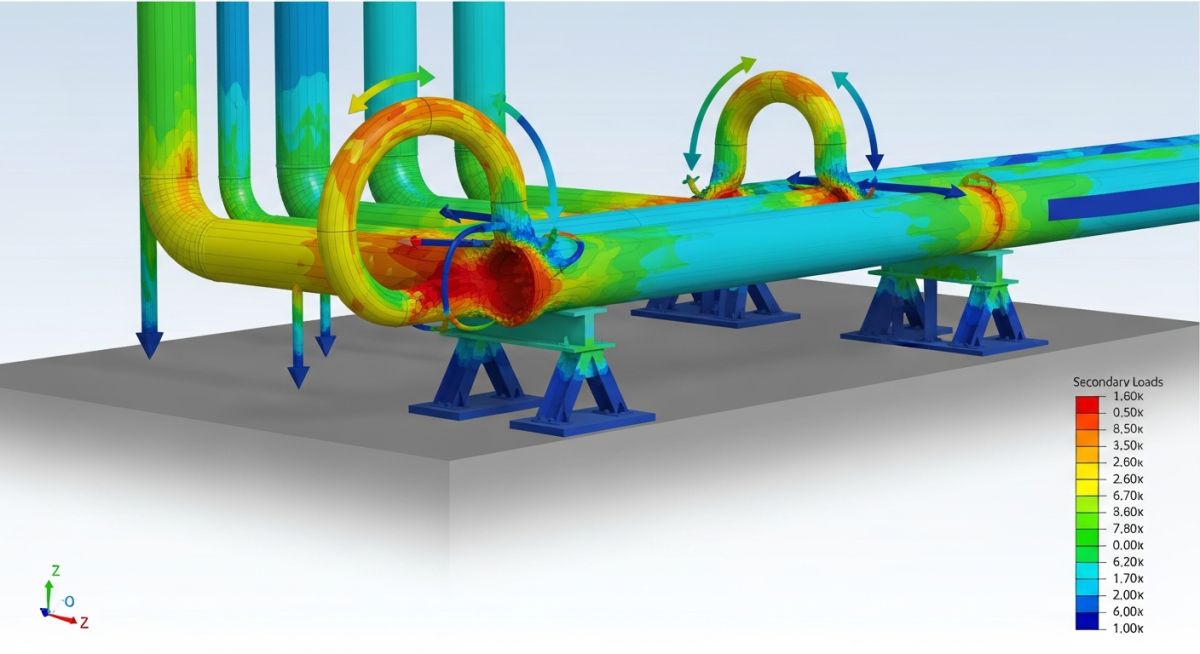
Secondary loads, by contrast, are self-limiting. Consider a hot process line constrained by two rigid anchors. As the pipe heats up, it wants to expand. If it cannot, it develops compressive stress. However, if that stress exceeds the yield point, the pipe material will locally deform (yield) to accommodate the displacement. Once the pipe has yielded, the stress is effectively capped at the yield strength of the material. This is the fundamental reason why we allow higher allowable stresses for thermal expansion (secondary) than for pressure (primary).
Field Warning: The Danger of Misclassification
Treating a secondary load as a primary load leads to “over-supporting.” If you place too many rigid supports to “control” thermal expansion, you actually prevent the pipe from naturally relieving its own stress. This creates high bending moments at nozzles and flanges, often leading to premature gasket leaks or nozzle cracks. Always verify your stress model’s displacement vectors before adding additional rigid restraints.
When performing stress analysis, we use the following hierarchy for primary loads:
- Internal Pressure: The most critical primary load; dictates the minimum wall thickness.
- Dead Weight: Includes the pipe, fluid, insulation, and valves. This must be supported by hangers or shoes to prevent sagging.
- External Forces: Wind, seismic, or relief valve thrust loads that act as sustained or transient primary forces.
For secondary loads, the focus shifts to flexibility analysis. We calculate the stress range (S_E) and compare it against the allowable stress range (S_A), which is defined as f * (1.25 * S_c + 0.25 * S_h). This formula accounts for the fatigue life of the system. By allowing the pipe to flex, we ensure that the thermal expansion does not consume the entire fatigue budget of the piping components.
Load Management Trade-offs: Effective piping design requires balancing the rigid requirements of primary load containment with the flexible requirements of secondary load dissipation to ensure long-term structural integrity.
Advantages of Proper Load Separation
- Optimized Material Usage: Correctly identifying secondary loads prevents unnecessary wall thickness increases.
- Extended Fatigue Life: Allowing thermal flexibility prevents premature crack initiation at high-stress points.
- Reduced Nozzle Loading: Proper flexibility analysis ensures equipment nozzles remain within allowable force/moment limits.
- Cost-Effective Support Design: Eliminates the need for excessive rigid restraints, reducing steel and labor costs.
Disadvantages of Mismanaged Loads
- Plastic Collapse Risk: Underestimating primary loads leads to catastrophic rupture under pressure.
- Gasket Leakage: Excessive secondary stress causes flange rotation and loss of seal integrity.
- Support Failure: Rigidly constraining thermal expansion can overload support structures and foundations.
- Operational Downtime: Fatigue-induced failures from secondary load mismanagement require frequent, costly maintenance shutdowns.
Industrial Load Application: From high-pressure steam headers to cryogenic transfer lines, the distinction between primary and secondary loads is the cornerstone of safe piping system architecture.
High-Pressure Steam Distribution
In steam headers, primary pressure loads dictate the schedule of the pipe, while thermal expansion from startup to operating temperature creates massive secondary loads. Engineers must utilize expansion loops or bellows to manage these secondary displacements without exceeding the allowable stress range defined by ASME B31.1.
Cryogenic Liquefied Natural Gas (LNG) Piping
LNG systems face extreme thermal contraction, which acts as a secondary load that can pull supports out of alignment. The design must incorporate cold-springing or specialized cryogenic supports to ensure that the contraction does not induce primary-level stresses on the pump suction nozzles.
Refinery Process Piping Networks
Complex refinery layouts involve multiple intersecting lines where primary weight loads from heavy valves and insulation must be balanced against secondary thermal growth. Using spring hangers allows the system to support the dead weight (primary) while simultaneously allowing the pipe to move freely during thermal cycles (secondary).
In my two decades of field experience, distinguishing between load types is the bedrock of ASME B31.3 compliance. Primary loads are force-controlled, meaning they do not self-limit; if the pipe cannot support the weight or pressure, it will continue to deform until failure occurs. Conversely, secondary loads are displacement-controlled, arising from thermal expansion or anchor movements. These are self-limiting because the stress relaxes as the pipe deforms, preventing catastrophic rupture under normal operating conditions.
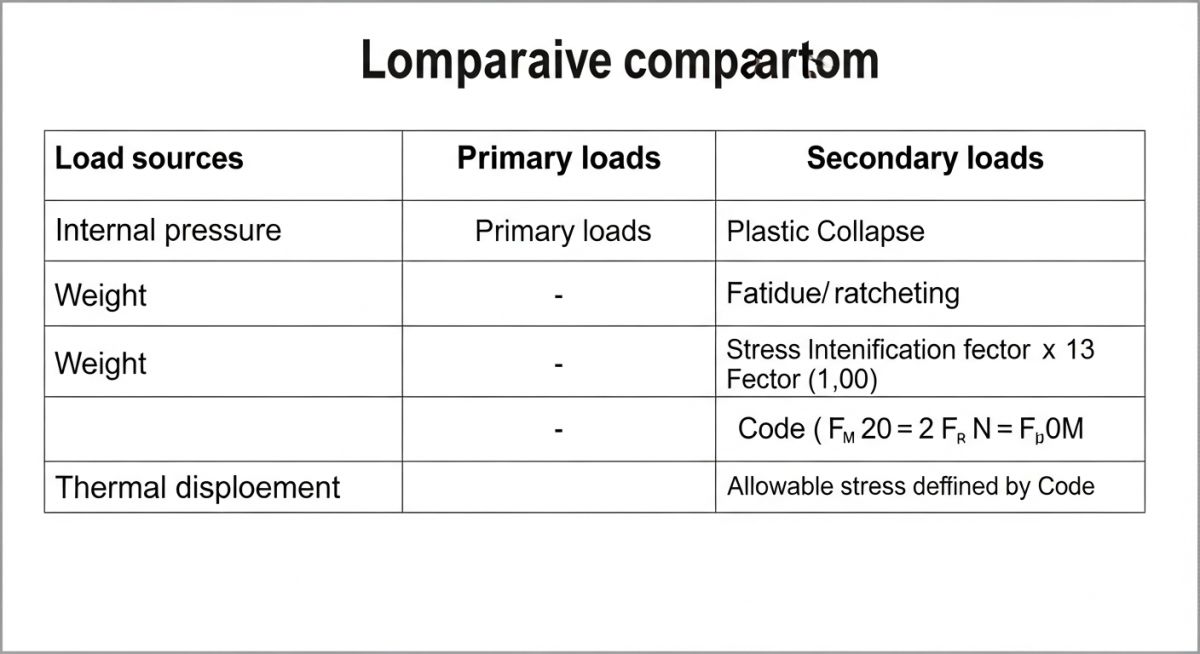
The following table summarizes how these loads interact with the piping system’s structural integrity. Understanding these parameters is vital for selecting appropriate support types, such as rigid struts for primary loads versus spring hangers for secondary thermal displacements. Always ensure your stress analysis software, whether Caesar II or AutoPIPE, correctly categorizes these inputs to avoid non-conservative design outcomes.
| Load Category | Source | Control Mechanism | ASME B31.3 Limit |
|---|---|---|---|
| Primary | Pressure, Weight | Force-controlled | Yield Strength (S) |
| Secondary | Thermal Expansion | Displacement-controlled | Allowable Range (Sa) |
The matrix below maps the physical entities of a piping system to their respective stress analysis requirements. When I review stress reports, I look for the correlation between the physical support location and the load type it is intended to mitigate. Misalignment here is a common cause of field failures, particularly in high-temperature process lines where thermal growth is underestimated.
By mapping these entities, engineers can ensure that the design basis aligns with the ASME B31.3 code requirements for sustained and expansion stress. This matrix serves as a quick reference for junior engineers to verify that every component—from the elbow to the nozzle—is accounted for in the global stress model.
| Entity | Primary Load Impact | Secondary Load Impact | Standard Ref |
|---|---|---|---|
| Pipe Wall | Hoop Stress | Bending Stress | ASME B31.3 |
| Support | Load Bearing | Friction/Constraint | MSS SP-58 |
| Nozzle | Reaction Force | Thermal Displacement | API 610/661 |
Piping Load Verification Protocol: Ensuring that the theoretical stress model matches the physical reality of the plant is the most critical step in my site commissioning process. A model is only as good as the data entered, and field conditions often deviate from the initial design assumptions. Use this checklist to validate that your primary and secondary load management strategies are correctly implemented on-site.
-
Weight Distribution: Verify that all heavy valves and inline components have dedicated supports to prevent excessive primary bending stresses. -
Thermal Clearance: Confirm that no rigid structures or temporary scaffolding impede the predicted thermal expansion path of the pipe. -
Spring Hanger Travel: Check that all variable spring hangers are set to the cold load position and are within the manufacturer’s travel range. -
Nozzle Loading: Inspect equipment nozzles for signs of misalignment or excessive strain, which often indicate an unmanaged secondary load. -
Support Integrity: Ensure all pipe shoes and clamps are properly tightened and that the sliding surfaces are free of debris to allow for thermal movement.
If any of these items fail verification, you must perform a re-analysis of the affected piping segment. Never assume that a minor deviation in support placement will not impact the overall stress profile, as piping systems are highly sensitive to changes in boundary conditions.
Problem: Excessive Nozzle Loading in High-Temperature Steam Line
- The steam line experienced unexpected leakage at the turbine nozzle flange during startup.
- Initial design failed to account for the thermal growth of the vertical riser section.
- Rigid supports were installed too close to the nozzle, preventing necessary thermal expansion.
- Secondary loads were converted into high-magnitude primary forces at the nozzle connection.
Outcome: Successful Mitigation and System Stabilization
- Replaced rigid supports with constant-load spring hangers to accommodate thermal displacement.
- Increased the flexibility of the piping loop by adding an expansion offset.
- Reduced nozzle reaction forces by 65 percent, well within the equipment manufacturer’s limits.
- Achieved successful startup without further flange leakage or structural deformation.
My recommendation for similar projects is to always perform a “cold-to-hot” walkdown. Observe the pipe movement during the initial heat-up phase to ensure that the actual displacement matches your stress model predictions. If you see a support lifting off its base or a spring hanger bottoming out, you have an immediate secondary load issue that requires correction before the system reaches full operating temperature.
Frequently Asked Engineering Questions
Why are primary loads considered non-self-limiting?
- Pressure loads act continuously regardless of the pipe’s shape.
- Weight loads are constant and do not relax with movement.
- ASME B31.3 requires these to be kept below the yield stress to ensure structural integrity.
How does thermal expansion create secondary loads?
- These are displacement-controlled, meaning the stress is a result of the forced movement.
- As the pipe yields slightly, the stress is redistributed, making it self-limiting.
- Proper design uses expansion loops to minimize these forces before they reach critical equipment.
What is the role of the stress range in ASME B31.3?
- It accounts for the cyclic nature of thermal expansion and contraction.
- The allowable stress range is typically higher than the yield stress because the load is self-limiting.
- This approach prevents premature failure due to thermal fatigue over the life of the plant.
Can primary and secondary loads be combined?
- Primary loads are checked against the yield strength to prevent bursting.
- Secondary loads are checked against the allowable range to prevent fatigue.
- Software tools perform these checks in distinct load cases to ensure full code compliance.
How do I select the right support for a specific load?
- Use spring hangers when the pipe must move vertically due to thermal expansion.
- Use guides or line stops to control lateral movement and prevent secondary stress buildup.
- Always consult MSS SP-58 for standard support types and their load-bearing capacities.
What happens if I ignore secondary loads in design?
- Thermal expansion forces can easily exceed the structural capacity of pump or turbine casings.
- Flange joints may lose their bolt preload, leading to hazardous process leaks.
- Long-term fatigue will eventually cause cracks at high-stress concentration points like branch connections.

📚 Recommended Resources: Primary loads and Secondary loads
Read these Guides
- 📄 Green Methanol Production: Engineering Requirements and Industrial Synthesis Pathways
- 📄 Green Ammonia Storage Systems Design and Industrial Safety Protocols
- 📄 Air Separation Unit Explained: Engineering Principles and Industrial Gas Production
- 📄 Rigid Struts: Definition, Applications, and Modeling in Caesar II