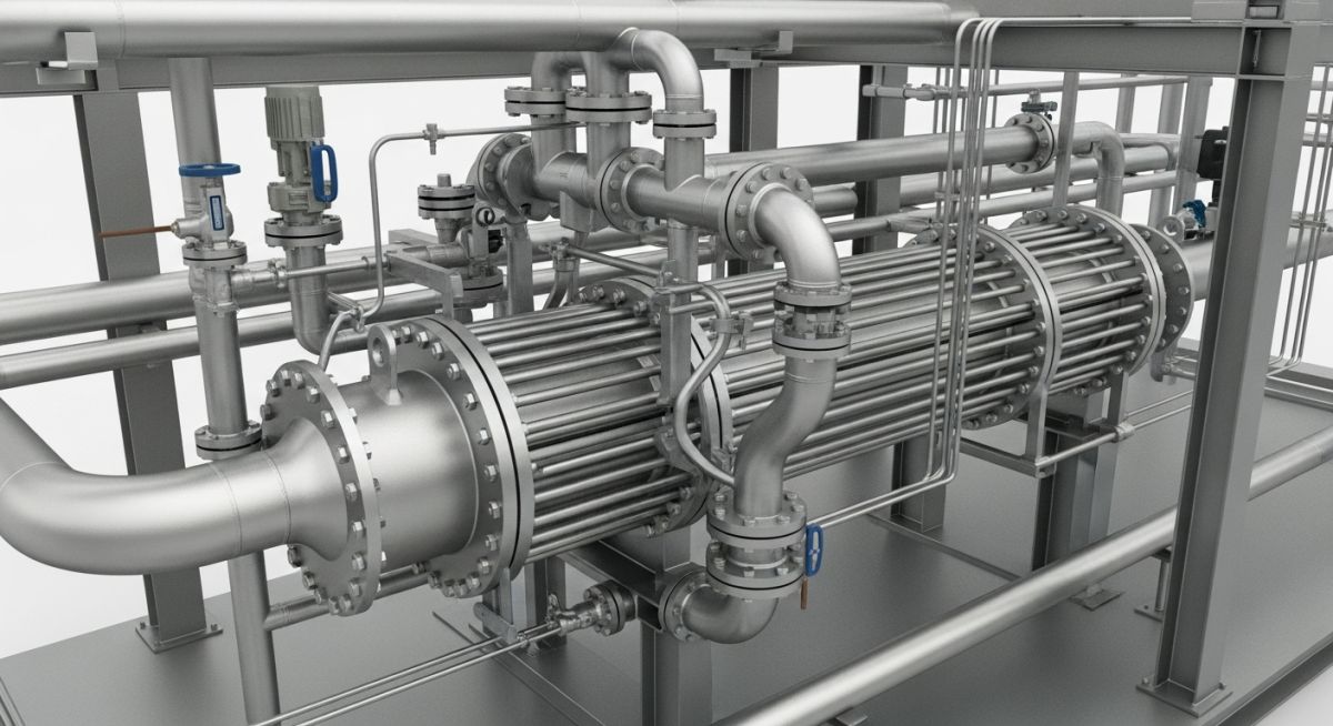
Shell and Tube Heat Exchanger Piping: Design and Stress Analysis
In my two decades of experience, I have observed that the most common failures in process plants stem from improper piping configuration around heat exchangers. When we design the piping for a shell and tube heat exchanger, we are not just connecting two points; we are managing complex thermal expansion, potential vibration, and strict nozzle load limitations imposed by the vessel manufacturer.
This guide provides the technical foundation for engineers to navigate the intersection of plant layout and stress analysis. We will explore how to balance the need for maintenance access with the rigid requirements of thermal flexibility, ensuring your piping system remains compliant and operational under extreme process conditions.
Key Takeaways for Piping Engineers:
- Mastering the integration of ASME Section VIII nozzle load limits with ASME B31.3 piping stress analysis.
- Strategic placement of expansion loops and supports to mitigate thermal growth.
- Optimizing maintenance access for tube bundle removal without compromising structural integrity.
- Implementing vibration control measures for high-velocity shell-side flow regimes.
Shell and Tube Heat Exchanger Piping Stress Analysis
Shell and Tube Heat Exchanger Piping Stress Analysis: This critical engineering process involves calculating the interaction between thermal expansion forces and the allowable nozzle loads defined by the vessel manufacturer to prevent mechanical failure.
When analyzing these systems, I always start by verifying the nozzle load limits provided in the vessel data sheet. These limits are often significantly lower than the piping code allowable stresses because the exchanger shell is susceptible to local deformation. If the piping imposes forces exceeding these limits, the shell-to-nozzle weld can crack, leading to catastrophic process leaks.
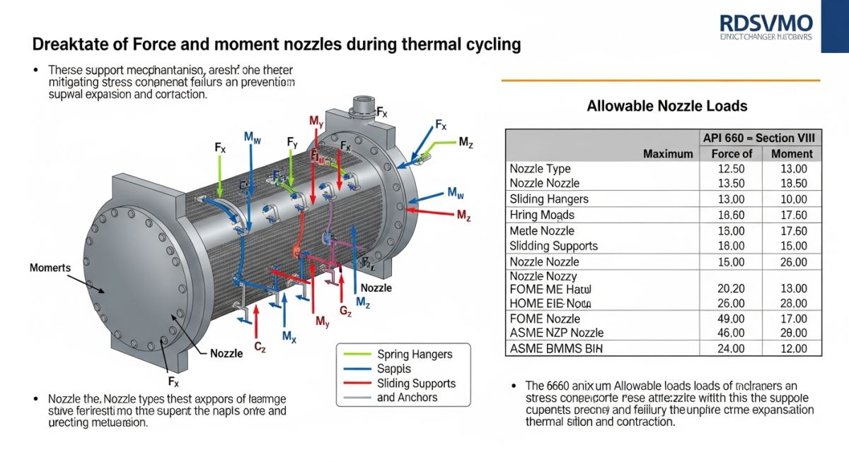
To manage thermal expansion, we utilize the flexibility of the piping layout. The fundamental equation for thermal expansion is delta L equals alpha times L times delta T. In a shell and tube exchanger, the shell and the tube bundle often operate at different temperatures, creating a differential expansion that must be absorbed by the piping connected to the nozzles.
Field Warning: Nozzle Load Sensitivity
Never assume that standard piping support spacing is sufficient for exchanger nozzles. The local stiffness of the exchanger shell is often much lower than the piping itself. Always perform a formal stress analysis using software like CAESAR II to ensure that the nozzle loads remain within the manufacturer’s specified limits, typically found in the vessel’s mechanical design report.
When designing the layout, I prioritize the use of expansion loops or offsets to provide the necessary flexibility. If the space is constrained, we may need to incorporate bellows expansion joints, though these introduce their own set of risks, such as pressure thrust forces that must be restrained by heavy-duty anchors. Every anchor point must be designed to withstand the full pressure thrust force, calculated as the product of the internal pressure and the effective area of the bellows.
Furthermore, we must consider the maintenance requirements. The piping must be routed to allow for the removal of the channel head or the entire tube bundle. This often requires the use of break-out spools or flanged connections located strategically to minimize the amount of piping that needs to be dismantled during a turnaround. I always ensure that these spools are supported independently so that the removal of one section does not cause the remaining piping to sag or lose its alignment.
Exchanger Piping Configuration Trade-offs: This assessment evaluates the technical benefits and operational limitations of various piping routing strategies for heat transfer equipment in high-pressure process environments.
Advantages
- Enhanced thermal flexibility through optimized loop geometry.
- Improved maintenance turnaround times with strategic break-out spools.
- Reduced nozzle stress concentrations via flexible piping routing.
- Better vibration damping through optimized support placement.
- Increased system reliability by adhering to strict ASME B31.3 standards.
Disadvantages
- Increased initial capital expenditure for complex piping layouts.
- Higher structural steel requirements for supporting long expansion loops.
- Potential for increased pressure drop due to additional elbows and fittings.
- Complexity in managing thermal thrust forces at anchor points.
- Risk of fatigue failure if vibration frequencies are not properly analyzed.
Industrial Heat Exchanger Integration: These applications demonstrate the practical implementation of piping stress analysis and layout design across diverse high-temperature and high-pressure industrial sectors.
Refinery Crude Pre-heat Trains
In crude oil distillation units, heat exchangers operate at extreme temperatures and pressures. Proper piping layout is vital to manage the significant thermal expansion of the large-bore piping connecting these exchangers, preventing nozzle overload and ensuring long-term mechanical integrity during continuous operation.
Petrochemical Feedstock Cooling
High-velocity cooling systems in ethylene plants require precise piping design to mitigate flow-induced vibration. By utilizing advanced stress analysis, we can design piping configurations that decouple the exchanger nozzles from the main process headers, effectively isolating the vessel from external piping vibrations.
Cryogenic Gas Processing
In LNG facilities, the extreme temperature differentials between ambient conditions and cryogenic process fluids necessitate specialized piping design. We employ complex expansion loops and cryogenic-rated supports to accommodate the massive contraction of the piping, ensuring that nozzle loads remain within the stringent limits required for low-temperature service.
High-Pressure Synthesis Loops
Ammonia and methanol synthesis plants utilize high-pressure heat exchangers that are highly sensitive to external moments. Our piping layout strategy focuses on minimizing the moment arm at the nozzle interface, often requiring the use of spring hangers and constant-load supports to maintain alignment during thermal cycling.
When designing piping connections for shell and tube heat exchangers, engineers must strictly adhere to ASME B31.3 for pressure piping and ASME Section VIII for the vessel nozzles. The following table outlines the critical design parameters that dictate the layout strategy, specifically focusing on thermal expansion, nozzle load limitations, and support requirements. These values serve as the baseline for stress analysis models in software like CAESAR II or AutoPIPE.
It is imperative to recognize that nozzle flexibility is often the limiting factor in exchanger piping. Exceeding the allowable loads defined by the manufacturer—or the WRC 107/297 bulletins—can lead to shell distortion, tube sheet leakage, or catastrophic flange failure. Always verify the specific design temperature and pressure ratings against the piping class specifications before finalizing the routing.
| Parameter | Standard/Reference | Design Consideration |
|---|---|---|
| Nozzle Load Limits | WRC 107/297 | Local stress at shell-nozzle junction |
| Thermal Expansion | ASME B31.3 | Flexibility analysis for hot service |
| Flange Leakage | ASME B16.5 | Bolt torque and gasket seating |
| Support Spacing | ASME B31.3 Table 321 | Preventing sagging and vibration |
The data above highlights the necessity of integrating mechanical vessel data with piping layout early in the project lifecycle. Failure to account for these parameters during the FEED stage often results in costly field rework or the addition of unnecessary expansion loops.
The following matrix maps the essential technical entities involved in Shell and Tube Heat Exchanger Piping. By categorizing these components, we ensure that every aspect of the piping system—from the nozzle interface to the support structure—is accounted for in the stress analysis report. This mapping is vital for maintaining compliance with international codes and internal quality assurance protocols.
In my experience, the most common oversight occurs when the piping engineer fails to coordinate the “anchor point” definition with the vessel engineer. If the exchanger is floating-head type, the thermal growth of the shell must be treated as a displacement vector in the piping stress model. This matrix provides a clear reference for identifying these critical interface points during the design review process.
| Entity | Acronym | Standard |
|---|---|---|
| Shell and Tube Heat Exchanger | STHE | TEMA |
| Pressure Piping Code | B31.3 | ASME |
| Welding Research Council | WRC | WRC 107 |
| Pipe Stress Analysis | PSA | ASME B31.3 |
Utilizing this matrix during the design phase allows for a systematic approach to identifying potential failure modes. By cross-referencing these entities, you can ensure that your piping layout remains within the allowable stress ranges defined by the governing codes.
Exchanger Piping Layout Verification: Before finalizing the piping layout, it is essential to perform a comprehensive site verification. This checklist ensures that all physical constraints, thermal expansion requirements, and maintenance access needs are met according to ASME B31.3 standards. Use this guide to validate your design against the actual field conditions.
-
☐
Verify nozzle orientation matches the P&ID and the certified vessel drawing from the manufacturer. -
☐
Confirm that the piping support locations do not interfere with the removal of the exchanger channel head or tube bundle. -
☐
Check for adequate clearance for bolt tightening and gasket replacement on all flange connections. -
☐
Ensure that thermal expansion loops are correctly positioned to prevent excessive nozzle loads on the shell. -
☐
Validate that the piping high-point vents and low-point drains are accessible for maintenance operations. -
☐
Confirm that the piping weight is not being supported by the exchanger nozzle itself; use spring hangers where necessary.
In my experience, the most common field issues arise from neglecting the “pull-space” required for tube bundle maintenance. Always ensure that the piping layout allows for the bundle to be extracted without requiring the removal of major piping spools. If space is limited, consider using spool pieces with quick-disconnect flanges to facilitate easier maintenance access while maintaining structural integrity.
The Problem: Excessive Nozzle Loading
During the commissioning of a high-temperature refinery heat exchanger, we observed significant leakage at the shell-side inlet flange. The investigation revealed that the piping layout did not account for the thermal expansion of the shell, leading to excessive bending moments on the nozzle.
- Rigid piping configuration restricted thermal growth.
- Nozzle loads exceeded the manufacturer’s allowable limits by 40%.
- Lack of flexibility analysis during the initial design phase.
- Thermal expansion of the shell was not treated as a displacement in the stress model.
The Outcome: Successful Remediation
We successfully resolved the issue by implementing a redesigned piping loop and installing a spring-loaded support system to accommodate the thermal displacement.
- Reduced nozzle loads to within 85% of the allowable limit.
- Eliminated flange leakage through proper gasket seating and bolt torque.
- Improved system flexibility by adding a U-bend expansion loop.
- Validated the new design using updated CAESAR II stress analysis.
My recommendation for similar projects is to always perform a sensitivity analysis on the nozzle loads during the design phase. By treating the exchanger as a flexible component rather than a rigid anchor, you can anticipate potential issues before they manifest as costly field failures.
Frequently Asked Engineering Questions
How do I determine the allowable nozzle loads for an exchanger?
- Request the specific design pressure and temperature ratings for the nozzle.
- Use finite element analysis (FEA) to determine the local stress at the junction.
- Ensure the combined stress does not exceed the allowable limits defined in ASME Section VIII, Division 2.
What is the impact of thermal expansion on shell-side piping?
- Cause flange leakage due to uneven bolt loading.
- Result in permanent deformation of the nozzle neck.
- Increase the risk of fatigue failure at the nozzle-to-shell weld.
Always incorporate expansion loops or flexible piping configurations to absorb this movement.
How should I support piping connected to a floating-head exchanger?
- Avoid placing rigid supports near the floating end of the exchanger.
- Use spring hangers to allow for vertical and axial movement.
- Ensure that the piping layout does not restrict the natural thermal growth of the shell.
Consult the TEMA standards for specific guidance on floating-head design requirements.
Are there specific ASME B31.3 requirements for exchanger piping?
- Flexibility analysis to ensure thermal stresses remain within allowable limits.
- Proper selection of flange ratings based on the design temperature.
- Compliance with welding and inspection requirements for high-pressure service.
Always refer to the latest edition of the code for current compliance standards.
What is the role of TEMA in exchanger piping layout?
- Defining the required maintenance clearances for tube bundle removal.
- Specifying nozzle orientation and reinforcement requirements.
- Providing guidelines for the design of exchanger supports and foundations.
Adhering to TEMA ensures that your piping layout is compatible with the exchanger’s mechanical design.
How do I prevent vibration in exchanger piping?
- Increase the stiffness of the piping system by adding supports or snubbers.
- Avoid long, unsupported spans of pipe near the exchanger nozzles.
- Perform a vibration analysis if the operating conditions involve high-velocity fluids or reciprocating equipment.
Proper support design is the most effective way to prevent long-term fatigue failure caused by vibration.
📚 Recommended Resources: Shell and Tube Heat Exchanger Piping
Read these Guides
- 📄 Design Considerations for a Piping System with an Expansion Bellow
- 📄 Pressure Vessel Design: Engineering Standards, Materials, and Support Systems
- 📄 Strategic Location of Static Equipment: Fired Heaters, Reactors, and Drums
- 📄 Pressure Vessel Design: Mastering Pressure and Temperature Safety Limits
🎓 Advanced Training


Complete Course on
Piping Engineering
Check Now
Key Features
- 125+ Hours Content
- 500+ Recorded Lectures
- 20+ Years Exp.
- Lifetime Access
Coverage
- Codes & Standards
- Layouts & Design
- Material Eng.
- Stress Analysis
