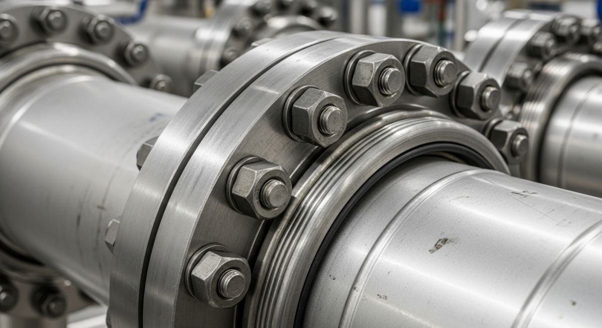
Selection of Pipe Flanges in Industrial Piping Systems
In my two decades of field experience, I have seen far too many projects suffer from premature joint failure simply because the initial selection of pipe flanges was treated as a commodity purchase rather than a critical engineering decision. A flange is not merely a connector; it is the primary interface between your piping system and the containment of hazardous fluids.
Choosing the correct flange requires a deep understanding of the interaction between internal pressure, operating temperature, and the chemical nature of the process fluid. Whether you are dealing with cryogenic services or high-temperature steam, the margin for error is non-existent. This guide provides the technical framework I use to evaluate flange compatibility, ensuring your piping systems meet the rigorous demands of modern industrial environments.
Key Takeaways for Engineers:
- Mastering the pressure-temperature ratings defined in ASME B16.5.
- Understanding the impact of flange facing types on gasket seating stress.
- Selecting materials that prevent galvanic corrosion and hydrogen embrittlement.
- Aligning bolt load calculations with flange rigidity requirements.
Technical Deep-Dive: Selection of Pipe Flanges
Flange Engineering Standards: The rigorous application of ASME B16.5 and ASME B16.47 to determine the structural integrity of bolted joints under varying thermal and mechanical loads.
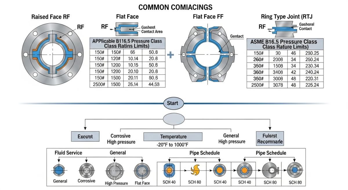
When I approach the selection of pipe flanges, I start with the pressure-temperature (P-T) rating. ASME B16.5 provides the baseline for flanges up to 24 inches, while ASME B16.47 covers larger diameters. The P-T rating is not a static number; it is a function of the material group and the operating temperature. As temperature increases, the allowable pressure for a given flange class (e.g., 150, 300, 600) decreases significantly due to the reduction in material yield strength.
Consider the material group. A carbon steel flange (ASTM A105) behaves differently than a stainless steel flange (ASTM A182 F316) at elevated temperatures. I always verify the material against the ASME Boiler and Pressure Vessel Code to ensure the material is permitted for the intended service. If your process involves cyclic loading or thermal shock, the flange rigidity becomes just as important as the pressure rating.
Field Warning: Flange Misalignment
Never force a flange into alignment by tightening bolts unevenly. This induces significant bending moments on the flange neck and can lead to catastrophic gasket failure. Always ensure the piping spool is properly supported and the flange faces are parallel within the tolerances specified in ASME PCC-1.
The selection of the flange face type—Raised Face (RF), Flat Face (FF), or Ring Type Joint (RTJ)—is dictated by the gasket type and the required seal integrity. For high-pressure, high-temperature hydrocarbon services, I almost exclusively specify RTJ flanges. The metal-to-metal contact of the ring gasket provides a superior seal that is less susceptible to blowout compared to spiral-wound gaskets used in RF flanges.
Finally, we must calculate the bolt load. The total bolt load must be sufficient to seat the gasket and maintain a residual load under the maximum internal pressure. I use the formulas provided in ASME Section VIII, Division 1, Appendix 2, to calculate the required bolt area. If the calculated bolt stress exceeds the allowable stress for the bolting material (e.g., ASTM A193 B7), you must either increase the flange class or select a higher-strength bolting material.
Flange Joint Performance: A comparative analysis of mechanical bolted connections versus welded alternatives in industrial piping infrastructure.
Advantages
- Facilitates easy disassembly for maintenance and internal inspection.
- Allows for the connection of dissimilar materials (e.g., carbon steel to stainless steel) using insulating kits.
- Provides a reliable seal for high-pressure applications when using RTJ facings.
- Simplifies the replacement of damaged piping sections without cutting or re-welding.
Disadvantages
- Higher potential for fugitive emissions compared to fully welded joints.
- Requires periodic bolt tensioning and maintenance to prevent leaks.
- Increased weight and space requirements compared to butt-welded connections.
- Susceptible to thermal fatigue and leakage during rapid temperature cycling.
Industrial Piping Deployment: Strategic implementation of flange connections across diverse process sectors to ensure operational safety and maintenance accessibility.
Refinery Hydrocracking Units
In high-pressure hydrocracking units, the selection of heavy-duty RTJ flanges is critical to withstand extreme hydrogen partial pressures. These flanges must be paired with high-strength bolting and specialized gaskets to prevent hydrogen-induced cracking and ensure long-term containment of volatile hydrocarbons.
Cryogenic LNG Processing
For liquefied natural gas (LNG) facilities, flange selection focuses on material toughness at temperatures as low as -162 degrees Celsius. We specify austenitic stainless steel flanges that maintain ductility at cryogenic temperatures, preventing brittle fracture during rapid cool-down cycles.
High-Pressure Steam Distribution
Steam headers in power plants require flanges capable of handling significant thermal expansion and contraction. We utilize raised-face flanges with spiral-wound gaskets, ensuring the joint can accommodate the mechanical stress induced by the high-velocity steam flow and thermal cycling.
Selecting the correct flange rating is the most critical step in ensuring the integrity of a pressurized piping system. The pressure-temperature ratings defined in ASME B16.5 dictate the maximum allowable non-shock pressure for a given material at a specific operating temperature. As temperatures rise, the allowable pressure capacity of the flange material decreases significantly, necessitating a careful review of the service conditions against the standard tables.
Engineers must verify that the chosen flange class (e.g., 150, 300, 600) remains within the safe operating envelope throughout the entire process cycle, including potential thermal excursions. Failure to account for these derating factors can lead to gasket blowouts, bolt relaxation, or catastrophic flange face separation. The following table provides a simplified overview of how these classes correlate to nominal pressure limits at ambient conditions, though actual design must always reference the specific material group tables found in the standard.
| Flange Class | Nominal Pressure (psi) | Typical Application |
|---|---|---|
| Class 150 | 285 psi (at 100F) | Low-pressure utility lines |
| Class 300 | 740 psi (at 100F) | Process piping, hydrocarbons |
| Class 600 | 1480 psi (at 100F) | High-pressure steam, oil/gas |
| Class 900 | 2220 psi (at 100F) | Critical transmission lines |
Always remember that these values are based on carbon steel materials like ASTM A105. When utilizing stainless steel or exotic alloys, the pressure-temperature curves shift, and you must consult the specific material group tables to avoid under-designing the connection.
The following matrix maps the essential technical entities required for professional flange specification. In my experience, the most common errors in piping design stem from a mismatch between the flange facing type and the gasket material, or a failure to align the bolt material with the flange pressure class. This matrix serves as a quick-reference guide to ensure all critical parameters are addressed during the procurement and design verification phases.
By standardizing these inputs, engineering teams can reduce the risk of procurement errors and site-level installation delays. Each entity listed below is governed by specific ASME or ASTM standards that must be strictly followed to maintain the certification of the piping system.
| Component | Standard Reference | Key Parameter |
|---|---|---|
| Flange Body | ASME B16.5 | Pressure-Temperature Rating |
| Bolting | ASTM A193/A194 | Yield Strength/Hardness |
| Gasket | ASME B16.20/B16.21 | Seating Stress/Leakage |
| Facing | ASME B16.5 | Surface Finish (Ra) |
This matrix should be integrated into your project’s piping material specification (PMS) to ensure consistency across all engineering disciplines. Always verify that the selected bolting material is compatible with the flange material to prevent galvanic corrosion in harsh environments.
Proper flange installation is the final line of defense against leaks in industrial piping. Even the most perfectly specified flange will fail if the installation practices are substandard. This checklist is designed for site engineers and inspectors to verify that the assembly meets the requirements of ASME PCC-1, which provides guidelines for pressure boundary bolted flange joint assembly.
- Surface Inspection: Check flange faces for scratches, radial tool marks, or corrosion that could compromise the gasket seal.
- Alignment Verification: Ensure the flange faces are parallel within the tolerances specified in the project piping specification.
- Gasket Selection: Confirm the gasket material is chemically compatible with the process fluid and rated for the design temperature.
- Bolt Lubrication: Verify that bolt threads are clean and properly lubricated to ensure accurate torque application.
- Torque Pattern: Use a star-pattern tightening sequence to ensure uniform gasket compression across the entire flange face.
- Final Inspection: Perform a post-tightening check to verify that the gap between flanges is uniform around the circumference.
Site verification is not merely a formality; it is a critical safety step. If you encounter a flange that requires excessive force to align, stop immediately. Forcing a flange into position introduces significant residual stress into the piping system, which can lead to premature fatigue failure or bolt snapping during thermal cycling. Always document the final torque values and the identity of the technician performing the work to maintain a clear audit trail for quality assurance purposes.
The Problem: Chronic Leakage in High-Temperature Steam Service
- Repeated gasket failures occurred on a 6-inch Class 600 flange connection during startup and shutdown cycles.
- Investigation revealed that the original design utilized a standard spiral-wound gasket that could not accommodate the rapid thermal expansion of the piping.
- The flange faces showed signs of “dishing” due to excessive bolt loading applied by maintenance crews attempting to stop the leaks.
- The piping stress analysis failed to account for the high bending moments imposed on the flange by the adjacent support configuration.
The Outcome: Successful Remediation and System Stability
- Replaced the standard gasket with a high-performance, inner-ring reinforced spiral-wound gasket designed for thermal cycling.
- Implemented a controlled bolting procedure using hydraulic tensioners to ensure uniform bolt stress across all studs.
- Modified the pipe support layout to reduce the bending moment acting on the flange connection.
- The system has operated for three years without a single leak, confirming the effectiveness of the revised design and installation protocol.
My recommendation for similar high-temperature applications is to prioritize the use of controlled bolting techniques. Relying on manual torque wrenches for large-diameter, high-pressure flanges often leads to uneven gasket seating, which is the primary cause of leakage in steam service. Always involve a stress engineer when dealing with recurring flange leaks, as the root cause is frequently external piping loads rather than the flange itself.
How do I determine the correct flange rating for my process?
- Identify the material group of your flange (e.g., Carbon Steel A105).
- Locate the pressure-temperature rating table for that specific material group.
- Ensure the design pressure at the operating temperature does not exceed the allowable limit for the chosen class.
- Always include a safety margin for potential process excursions or pressure surges.
Can I mix different flange pressure classes in the same line?
- Ensure the lower-rated flange is protected by a pressure relief device if the system pressure can exceed its rating.
- Verify that the bolt patterns are compatible, as some classes have different bolt circle diameters.
- Document the transition in the piping isometric drawings to prevent maintenance errors.
- Avoid this practice whenever possible to simplify spare parts management and reduce the risk of human error during installation.
What is the significance of the flange facing finish?
- Standard serrated finishes (125-250 micro-inches Ra) are designed to “bite” into soft gaskets.
- Smooth finishes are required for metal-to-metal gaskets or O-ring seals.
- Incorrect surface finishes can lead to leakage paths, especially in high-pressure or hazardous fluid services.
- Always inspect the flange face for radial scratches, which act as direct leak paths regardless of the surface finish.
How does bolt material affect flange integrity?
- Use high-strength bolting like ASTM A193 Grade B7 for most industrial applications.
- Ensure the bolt yield strength is compatible with the flange pressure class to avoid bolt stretching or snapping.
- Consider corrosion resistance in the selection process, especially in offshore or chemical plant environments.
- Never substitute lower-grade bolts, as this can lead to catastrophic joint failure under load.
What are the risks of over-tightening flange bolts?
- Flange “dishing” occurs when the flange face bends inward, causing a loss of contact at the outer diameter.
- Gasket crushing can destroy the sealing element, leading to immediate or delayed leakage.
- Bolt fatigue is accelerated when bolts are tightened beyond their design limits.
- Always use calibrated torque tools and follow the manufacturer’s recommended torque values to ensure safe and reliable assembly.
When should I use a blind flange?
- Use blind flanges for temporary isolation during maintenance or system modifications.
- Ensure the blind flange is rated for the same pressure and temperature as the rest of the piping system.
- Verify that the bolting and gasket requirements are met, just as you would for a standard flange connection.
- Always follow proper lockout/tagout procedures when installing or removing blind flanges in active process lines.
📚 Recommended Resources: Selection of Pipe Flanges
Read these Guides
🎓 Advanced Training


Complete Course on
Piping Engineering
Check Now
Key Features
- 125+ Hours Content
- 500+ Recorded Lectures
- 20+ Years Exp.
- Lifetime Access
Coverage
- Codes & Standards
- Layouts & Design
- Material Eng.
- Stress Analysis
