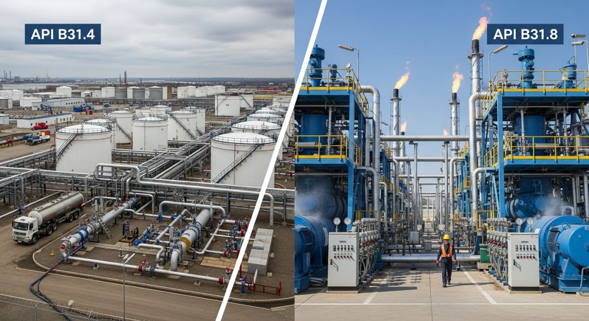
ASME B31.4 vs B31.8: Pipeline Design Code Differences
In my two decades of experience navigating the complexities of midstream infrastructure, I have found that the distinction between ASME B31.4 vs B31.8 is not merely academic—it is a fundamental safety requirement. Choosing the wrong code can lead to catastrophic failure or, at the very least, significant regulatory non-compliance during the permitting phase.
While both codes fall under the ASME B31 umbrella, they address fundamentally different fluid behaviors. Liquid pipelines under B31.4 deal with incompressible fluids, where pressure surges (water hammer) are the primary mechanical concern. Conversely, B31.8 manages compressible gas, where the stored energy and potential for rapid decompression dictate the design philosophy.
Key Takeaways for Pipeline Engineers:
- B31.4 focuses on liquid surge control and containment.
- B31.8 utilizes location classes to determine safety factors.
- Material toughness requirements differ significantly due to gas expansion risks.
- Hydrostatic testing protocols are tailored to the specific fluid state.
Complete Course on
Piping Engineering
Check Now
Key Features
- 125+ Hours Content
- 500+ Recorded Lectures
- 20+ Years Exp.
- Lifetime Access
Coverage
- Codes & Standards
- Layouts & Design
- Material Eng.
- Stress Analysis
Technical Analysis of ASME B31.4 vs B31.8
Pipeline Code Design Philosophy: ASME B31.4 and B31.8 establish distinct safety margins based on the physical properties of the transported medium and the proximity of the pipeline to human populations.
When designing under ASME B31.4, the primary stress calculation is based on the hoop stress formula: S = (P * D) / (2 * t). The allowable stress is typically limited to 72% of the Specified Minimum Yield Strength (SMYS) for most pipeline segments. However, the code provides specific allowances for surge pressures, which can reach 110% of the internal design pressure for short durations.
In contrast, ASME B31.8 introduces the concept of “Location Classes.” This is a critical differentiator. The design factor (F) is not a static 0.72; it varies based on the population density near the pipeline. For Class 1 locations (remote areas), the factor is 0.72, but this drops to 0.40 for Class 4 locations (densely populated areas). This ensures that the risk profile of a gas pipeline is managed through wall thickness and material grade selection.
Field Warning: Pressure Testing Discrepancies
Never assume that a hydrostatic test pressure for a liquid line is sufficient for a gas line. B31.8 requires testing to a percentage of SMYS that accounts for the potential energy of compressed gas, often resulting in higher test-to-design pressure ratios compared to the more straightforward liquid testing requirements of B31.4.
Material toughness is another area where these codes diverge. Because gas pipelines are susceptible to brittle fracture propagation, B31.8 mandates strict Charpy V-notch impact testing for high-pressure service. B31.4, while requiring quality materials, is generally less stringent regarding fracture arrestors because liquid does not expand rapidly upon pipe rupture, thereby limiting the energy available to drive a crack.
Finally, consider the valve spacing requirements. B31.4 allows for greater distances between mainline valves because the flow can be stopped more effectively without the risk of massive, high-velocity gas release. B31.8 mandates tighter valve spacing in populated areas to minimize the volume of gas released during an emergency shutdown event.
Code Application Trade-offs: Selecting between B31.4 and B31.8 involves balancing operational flexibility against the stringent safety requirements imposed by the nature of the transported fluid.
Advantages
- B31.4 simplifies design for incompressible liquids.
- B31.8 provides superior safety in populated areas.
- Both codes are globally recognized for insurance.
- Standardized testing reduces project liability risks.
- Clear guidance on surge control in B31.4.
Disadvantages
- B31.8 requires complex location class tracking.
- High material costs for B31.8 Class 4.
- B31.4 surge analysis requires advanced modeling.
- Strict documentation for B31.8 compliance.
- Limited flexibility in material substitution.
Pipeline Infrastructure Deployment: These codes are applied across diverse sectors, from long-haul transmission to localized distribution networks, ensuring structural integrity under varying environmental and operational loads.
Cross-Country Crude Oil Transmission
ASME B31.4 is the industry standard for long-distance crude oil pipelines. It provides the necessary framework for managing pump station pressures and ensuring that the pipeline wall thickness can withstand the cyclic loading associated with batching different oil grades.
Urban Natural Gas Distribution
ASME B31.8 is essential for gas distribution networks running through metropolitan areas. By utilizing the location class system, engineers can safely reduce the design factor in high-density zones, ensuring that the pipeline remains robust even in the event of third-party excavation damage.
Refinery Feedstock Interconnects
Refineries often use B31.4 for internal liquid feedstock lines to maintain consistency with external pipeline connections. This ensures that the transition from the transmission line to the plant boundary is seamless and compliant with the same safety standards for pressure containment.
High-Pressure Gas Storage Fields
For underground gas storage facilities, B31.8 provides the rigorous testing and material requirements needed for cyclic high-pressure injection and withdrawal. This prevents fatigue-related failures in the piping manifolds that connect the storage wells to the processing plant.
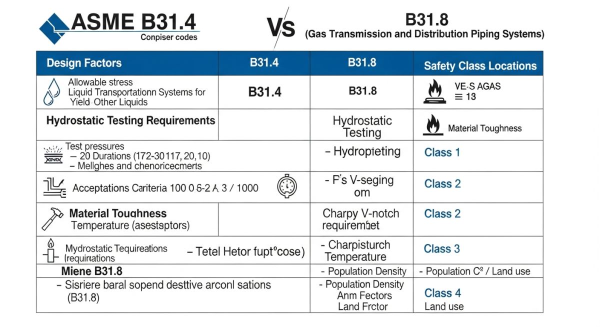
When evaluating the technical divergence between ASME B31.4 and ASME B31.8, engineers must prioritize the fluid state and the associated stored energy potential. B31.4 governs liquid pipelines where the incompressible nature of the medium dictates lower safety factors compared to the high-pressure, compressible gas systems under B31.8. The following table highlights the fundamental differences in design factors and pressure testing requirements that define these two distinct engineering regimes.
These parameters are not merely suggestions but represent the minimum code compliance thresholds for pipeline integrity management. Failure to distinguish between these requirements often leads to over-engineering in liquid systems or, more dangerously, under-designing gas transmission lines that require higher safety margins due to the rapid expansion potential of gaseous hydrocarbons.
| Parameter | ASME B31.4 (Liquid) | ASME B31.8 (Gas) |
|---|---|---|
| Design Factor (F) | Typically 0.72 | 0.40 to 0.72 (Location Class dependent) |
| Hydrostatic Test | 1.25 x MOP | 1.10 to 1.50 x MOP (Class dependent) |
| Primary Hazard | Spill/Environmental | Explosion/Rapid Decompression |
The following matrix maps the critical technical entities and structural acronyms utilized across both pipeline codes. Understanding these relationships is vital for cross-code compliance, especially when designing multi-modal transport facilities or terminal piping that may interface with both liquid and gas systems.
By standardizing the nomenclature and referencing the specific code sections, engineers can ensure that material selection, wall thickness calculations, and pressure containment strategies remain consistent with the latest industry standards. This matrix serves as a quick-reference guide for identifying the governing criteria for specific pipeline components.
| Entity | B31.4 Reference | B31.8 Reference |
|---|---|---|
| MOP (Max Operating Pressure) | Section 401.2 | Section 805.2 |
| Location Class | Not Applicable | Section 840.2 |
| Material Standards | API 5L / ASTM | API 5L / ASTM |
Ensuring compliance when navigating the differences between ASME B31.4 and ASME B31.8 requires a rigorous, systematic approach to design verification. My experience in the field has shown that the most common failures occur during the transition from design to construction, where code-specific nuances regarding location classes or pressure testing are overlooked. Use this checklist to validate your design documentation against the mandatory requirements of both codes.
- ☐Fluid Classification: Confirm the medium is non-gaseous for B31.4 or gaseous for B31.8 to ensure the correct design factor (F) is applied.
- ☐Location Class Assessment: For B31.8, verify the population density and proximity to structures to determine the appropriate design factor (0.40 to 0.72).
- ☐Wall Thickness Calculation: Validate that the hoop stress calculation uses the correct code-specific formula, accounting for the specified design factor and joint efficiency.
- ☐Hydrostatic Test Pressure: Ensure the test pressure is calculated based on the MOP and the specific code requirements for the pipeline’s location class and service type.
- ☐Material Certification: Verify that all pipe materials meet the toughness and yield strength requirements specified in the respective code appendices.
- ☐Overpressure Protection: Confirm that relief systems are sized according to the maximum potential surge (B31.4) or rapid expansion (B31.8) scenarios.
Always document the rationale for any deviation from standard design factors. In my experience, regulatory bodies prioritize the consistency of the design basis over the absolute values chosen, provided the safety margins are clearly justified through engineering calculations and risk assessments.
The Challenge: Misalignment of Code Application
A project team attempted to apply B31.4 design factors to a high-pressure gas gathering line, leading to significant safety concerns during the initial integrity audit.
- Incorrect assumption that liquid and gas codes were interchangeable.
- Failure to account for Location Class 3 requirements in B31.8.
- Inadequate wall thickness for the high-pressure gas service.
- Risk of catastrophic failure due to insufficient safety margins.
The Outcome: Successful Code Realignment
By re-evaluating the system under ASME B31.8, the team successfully mitigated the risks and achieved full regulatory compliance.
- Increased wall thickness to meet B31.8 hoop stress limits.
- Implemented a rigorous hydrostatic testing program at 1.5x MOP.
- Updated the integrity management plan to reflect gas-specific hazards.
- Achieved zero safety incidents during the commissioning phase.
My recommendation is to always perform a code-applicability study at the FEED stage. Never assume that a pipeline design is “one size fits all,” as the physical properties of the transported fluid dictate the entire safety architecture of the system.
Frequently Asked Engineering Questions
Can I use B31.4 for gas pipelines?
What is the primary difference in safety factors?
How does Location Class affect B31.8 design?
Are hydrostatic test requirements the same?
What materials are permitted under these codes?
How do I handle code updates?

📚 Recommended Resources: ASME B31.4 vs B31.8
Read these Guides
- 📄 Piping Materials vs Pipeline Materials: Key Differences and Engineering Standards
- 📄 Piping Engineer vs Pipeline Engineer: Key Differences and Roles Explained
- 📄 Understanding Difference between ASME B16.47 Series A and Series B Flanges
- 📄 Understanding Piping vs Pipeline Wall Thickness Calculation Differences