How to Select the Best Pipe Flange Gaskets for Piping Systems
In my 20+ years of managing piping integrity in petrochemical plants, I have seen millions of dollars lost due to a single, poorly selected gasket. It is easy to focus on heavy-walled pipes and massive valves, but the humble gasket is often the weakest link in any pressurized system. When a joint fails, it is rarely the steel flange that gives way; it is almost always the sealing element that has degraded, blown out, or been crushed under improper bolt loads.
Selecting the right gasket requires a deep understanding of fluid chemistry, temperature limits, pressure classes, and mechanical forces. In this guide, I will share my field experience and technical knowledge to help you navigate the complex landscape of gasket selection, ensuring your piping systems remain leak-free, safe, and compliant with international standards.
Key Engineering Takeaways
- Soft gaskets like PTFE and elastomers are ideal for low-pressure, low-temperature utility lines.
- Spiral wound and grooved metal (Kammprofile) gaskets dominate high-pressure, high-temperature hydrocarbon services.
- Ring Type Joint (RTJ) gaskets provide the ultimate metal-to-metal seal for extreme offshore and high-pressure applications.
- Proper bolt torque and flange alignment are just as critical as the gasket material itself.
Understanding the Primary Types of Pipe Flange Gaskets
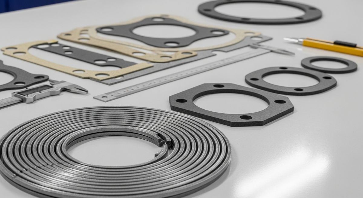
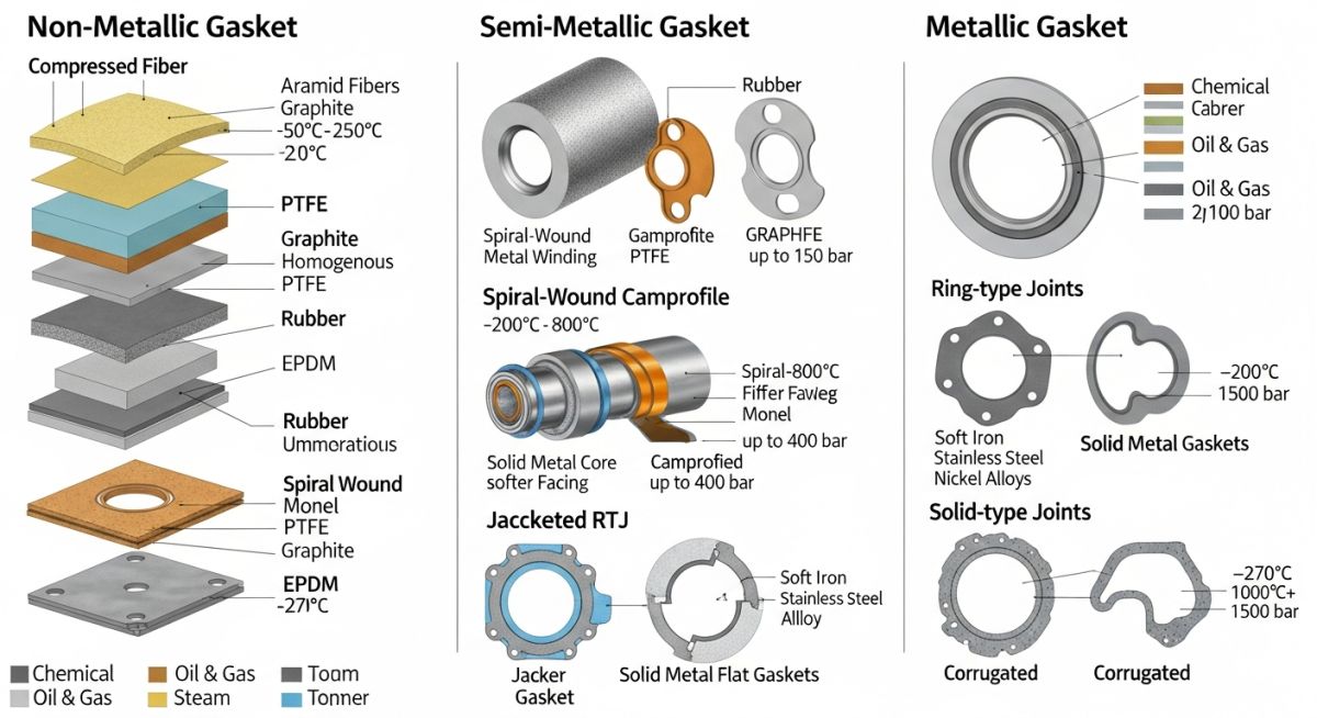
To select the correct sealing element, we must first categorize them by their material composition and mechanical behavior. In industrial piping, we classify these components into three primary groups: non-metallic (soft), semi-metallic (composite), and metallic. Each group serves a distinct range of operating pressures, temperatures, and chemical environments.
1. Non-Metallic (Soft) Gaskets
These are manufactured from flexible materials that compress easily under low bolt loads. They are typically used with flat-face or raised-face flanges in low-pressure classes (Class 150 and Class 300). Common materials include:
- Elastomers (Rubber, Neoprene, EPDM, Nitrile): Excellent for water, air, and low-pressure utility lines. They offer high flexibility but have limited temperature resistance, typically capped at 120 degrees Celsius.
- PTFE (Teflon): Outstanding chemical resistance across almost all media. However, pure PTFE is prone to “cold flow” or creep under load. To combat this, we use restructured or filled PTFE (such as silica or barium sulfate fillers) to maintain structural integrity.
- Compressed Non-Asbestos Fiber (CNAF): Formulated with synthetic fibers bonded with rubber. These have replaced asbestos in general-purpose steam, water, and mild chemical services.
2. Semi-Metallic (Composite) Gaskets
These combine metallic and non-metallic materials to leverage the strength of metal and the sealing efficiency of soft fillers. They are the workhorses of the oil, gas, and petrochemical industries, designed for high-pressure and high-temperature applications.
- Spiral Wound Gaskets (SWG): Constructed by winding a preformed V-shaped metal strip (typically Stainless Steel 316) with a soft filler material (graphite or PTFE). They are highly resilient and can handle thermal cycling and pressure surges. They comply with ASME B16.20.
- Kammprofile (Grooved Metal) Gaskets: Feature a solid metal core with concentric grooves on both sides, covered with a soft sealing layer (graphite or PTFE). They offer exceptional reliability in high-temperature, high-pressure services with lower required bolt loads than spiral wound alternatives.
- Metal Jacketed Gaskets: Consist of a soft filler core (graphite or ceramic) enclosed in a thin metal jacket. They are commonly used in heat exchangers but have largely been superseded by Kammprofile designs due to superior recovery properties.
3. Metallic Gaskets (Ring Type Joints – RTJ)
For extreme high-pressure (Class 600 to Class 2500) and high-temperature services, solid metal gaskets are required. These are designed to fit into machined grooves on the flange faces, creating a high-integrity metal-to-metal seal.
- Oval RTJ: The traditional design, providing a line contact seal. They require higher bolt loads to deform the metal and achieve a seal.
- Octagonal RTJ: A more modern design with a higher sealing efficiency than the oval type. The octagonal shape provides a surface contact seal, making it the preferred choice in modern high-pressure piping specifications.
Field Warning: Inward Buckling of Spiral Wound Gaskets
In my experience, using spiral wound gaskets without an inner ring in vacuum services or with PTFE filler is a recipe for disaster. Under high bolt loads or thermal expansion, the inner windings can buckle inward into the pipe bore. This restricts flow, damages downstream equipment like control valves, and ultimately destroys the seal. Always specify an inner ring (Style CG or CRI) for vacuum services, PTFE fillers, or flanges above Class 600.
Engineering Calculations: Gasket Design Parameters
To ensure a flange joint remains leak-free, we must calculate the minimum required bolt loads for both operating and seating conditions. These calculations are governed by ASME Section VIII Division 1 Appendix 2.
The minimum required bolt load for operating conditions (Wm1) must resist the hydrostatic end force of the design pressure while maintaining sufficient compression on the gasket:
The minimum required bolt load for gasket seating (Wm2) must be sufficient to deform the gasket material into the micro-grooves of the flange face under atmospheric conditions:
Where:
- G: Diameter at the location of the gasket load reaction (mm or inches).
- P: Internal design pressure (MPa or psi).
- b: Effective gasket seating width (mm or inches).
- m: Gasket factor (dimensionless ratio representing the ratio of residual gasket stress to internal pressure).
- y: Gasket seating stress or yield factor (MPa or psi).
| Gasket Type | Common Materials | Temp Range (°C) | Max Pressure Class | Primary Standard |
|---|---|---|---|---|
| Elastomeric Flat Gaskets | EPDM, Neoprene, Nitrile | -40 to 120 | Class 150 | ASME B16.21 |
| PTFE (Restructured) | PTFE with Silica/Barium Sulfate | -200 to 260 | Class 300 | ASME B16.21 |
| Spiral Wound (SWG) | SS316 with Graphite/PTFE Filler | -200 to 500 (Graphite) | Class 2500 | ASME B16.20 |
| Kammprofile | SS316 Core with Graphite Layers | -200 to 650 | Class 2500 | ASME B16.20 |
| Ring Type Joint (RTJ) | Soft Iron, Low Carbon Steel, SS316 | -200 to 800 | Class 2500 | ASME B16.20 |
| Entity / Acronym | Full Technical Name | Physical Parameter | Primary Function | Reference Standard |
|---|---|---|---|---|
| SWG | Spiral Wound Gasket | Winding density & thickness | High-pressure dynamic sealing | ASME B16.20 |
| RTJ | Ring Type Joint | Hardness (HBW) & dimensions | Metal-to-metal high-integrity seal | ASME B16.20 / API 6A |
| CNAF | Compressed Non-Asbestos Fiber | Tensile strength & compressibility | General utility fluid sealing | ASME B16.21 |
| PCC-1 | Pressure Boundary Joint Assembly | Target bolt torque values | Guidelines for pressure boundary assembly | ASME PCC-1 |
Site Verification Checklist for Gasket Installation
Even the highest-quality gasket will fail if installed incorrectly. In my experience, over 80% of flange leaks are caused by poor installation practices rather than material defects. Use this checklist on-site to ensure your team follows best practices before buttoning up any flange joint.
Pre-Assembly & Installation Checkpoints
-
Flange Face Inspection: Verify that the flange faces are clean, free of rust, scale, and deep radial scratches. Ensure the surface finish (e.g., 125-250 AARH for standard raised face) matches the gasket specification.
-
Flange Alignment: Check that the flange faces are parallel within 0.5 mm and that the bolt holes align perfectly without requiring external force.
-
Gasket Verification: Confirm that the gasket material, size, pressure class, and thickness match the piping isometric drawing and specification sheet.
-
Bolt and Nut Inspection: Ensure bolts and nuts are clean, free of burrs, and lubricated with an approved anti-seize compound on both the threads and the nut bearing faces.
-
Torque Sequence: Apply torque in a star pattern (cross-pattern) in incremental steps: 30% of target torque, 60% of target torque, and finally 100% of target torque. Perform a final rotational pass at 100% torque to ensure uniformity.
Field Case Study: Real-World Application
The Problem: Recurring Leaks in Hydrocracker Unit
During a major turnaround at a refinery, a 12-inch Class 900 flange joint on a hydrocracker feed line experienced recurring leaks during startup thermal cycling. The line operated at 380 degrees Celsius and 14.5 MPa. The original installation used a standard spiral wound gasket with a graphite filler but no inner ring. The maintenance crew had repeatedly over-torqued the bolts in an attempt to stop the leak, which only exacerbated the issue.
The Outcome: Redesign and Controlled Torque Protocol
I led the engineering investigation and discovered that the inner windings of the spiral wound gasket had buckled inward into the pipe bore. This was caused by the high bolt loads combined with thermal expansion of the pipe. We replaced the failed gasket with an ASME B16.20 compliant spiral wound gasket featuring both inner and outer rings (Style CRI) with a Stainless Steel 316L core and flexible graphite filler.
We also implemented a controlled torque protocol using hydraulic torque wrenches following ASME PCC-1 guidelines. The joint has remained completely leak-free for over four years of continuous operation, saving the refinery thousands of dollars in unplanned downtime and preventing potential safety hazards.
My direct recommendation for any high-pressure, high-temperature hydrocarbon service is to never compromise on gasket design. Always specify spiral wound gaskets with both inner and outer rings to prevent inward buckling and ensure structural stability under thermal cycling.
Selecting and Maintaining Pipe Flange Gaskets Safely
To help you make informed decisions in the field, I have compiled answers to some of the most common questions I encounter regarding the selection, installation, and maintenance of pipe flange gaskets.
What is the difference between ASME B16.20 and ASME B16.21?
The primary difference lies in the gasket materials and types they cover. ASME B16.20 governs metallic and semi-metallic gaskets, including spiral wound, jacketed, and ring joint gaskets. On the other hand, ASME B16.21 covers non-metallic (soft) flat gaskets designed for use with flat-face or raised-face flanges.
Why are inner rings recommended for spiral wound gaskets?
Inner rings act as a compression stop, preventing the metal windings from buckling inward into the pipe bore under high bolt loads or thermal expansion. They also protect the sealing element from erosion caused by turbulent process fluid and fill the void space between the flange face and the gasket, reducing dead spaces where solids can accumulate.
How do the gasket factor (m) and seating stress (y) affect flange design?
The gasket factor (m) represents the ratio of residual gasket stress to internal pressure required to maintain a seal during operation. The seating stress (y) is the minimum stress required to deform the gasket material into the flange face micro-grooves under atmospheric conditions. Both parameters are defined in ASME Section VIII Division 1 Appendix 2 and are used to calculate the minimum required bolt loads.
Can I reuse a pipe flange gasket after opening a joint?
No, you should never reuse a gasket. During installation, the gasket undergoes plastic deformation to fill the micro-grooves of the flange face. Once compressed, it loses its elasticity and recovery properties. Reusing a gasket almost always results in a joint leak, leading to costly downtime and safety hazards.
What is the difference between octagonal and oval RTJ gaskets?
Oval RTJ gaskets provide a line contact seal and can be used in both flat-bottom and round-bottom groove flanges. Octagonal RTJ gaskets provide a surface contact seal, which offers higher sealing efficiency but can only be used in flat-bottom groove flanges. Modern piping specifications generally prefer octagonal RTJ gaskets due to their superior sealing performance.
How does flange surface finish affect gasket selection?
The flange surface finish must match the gasket type to achieve a proper seal. Soft gaskets require a rougher finish (typically 125 to 250 micro-inches AARH) to “grip” the gasket and prevent extrusion. Metallic gaskets, like RTJs, require a very smooth finish (typically 63 micro-inches AARH or smoother) to achieve a tight metal-to-metal seal without excessive bolt load.
Complete Course on
Piping Engineering
Check Now
Key Features
- 125+ Hours Content
- 500+ Recorded Lectures
- 20+ Years Exp.
- Lifetime Access
Coverage
- Codes & Standards
- Layouts & Design
- Material Eng.
- Stress Analysis