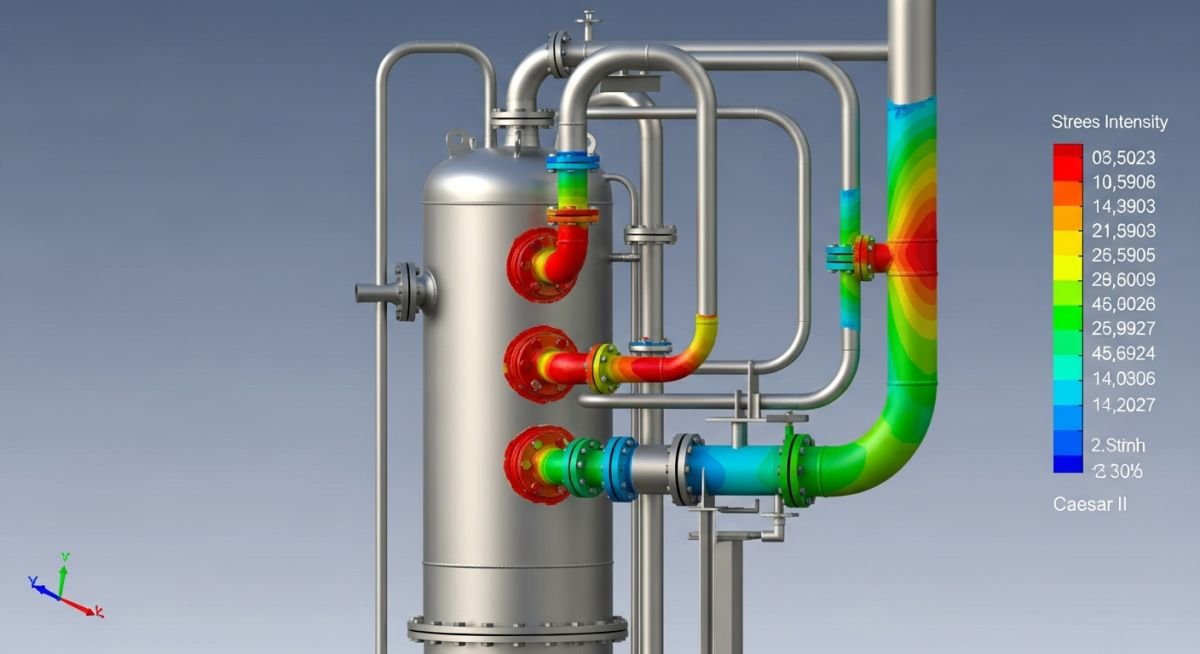
Stress Analysis of Vertical Reboiler Piping using Caesar II
In my two decades of experience, I have found that the vertical reboiler is one of the most challenging pieces of equipment to model correctly. Unlike horizontal vessels, the vertical orientation introduces unique thermal growth patterns that often lead to excessive nozzle loads if not managed through precise piping flexibility analysis.
When performing a stress analysis of vertical reboiler piping using Caesar II, you are not just checking for code compliance; you are protecting the integrity of the vessel’s shell and the reliability of the entire process unit. A minor oversight in modeling the thermal anchor or the nozzle stiffness can lead to catastrophic flange leakage or, worse, shell deformation during startup.
Key Takeaways for Your Next Project:
- Always verify nozzle stiffness values against WRC 107/297 or FEA results.
- Account for the vertical thermal growth of the vessel shell in your Caesar II model.
- Ensure that the piping support scheme allows for free thermal expansion without binding.
- Validate all load cases against the specific allowable limits provided by the vessel manufacturer.
Stress Analysis of Vertical Reboiler Piping
Vertical Reboiler Piping Analysis: A rigorous computational approach to modeling piping systems connected to vertical heat exchangers, focusing on the interaction between thermal expansion, vessel nozzle stiffness, and structural support constraints under ASME B31.3 criteria.
When I begin a stress analysis of vertical reboiler piping using Caesar II, the first step is establishing the correct coordinate system. Vertical vessels expand upward from their base support. If you model the piping as if the vessel is a rigid, stationary object, you will inevitably underestimate the nozzle loads during the hot operating condition.
Modeling Thermal Growth and Nozzle Stiffness
The vessel’s thermal growth is calculated as the product of the coefficient of thermal expansion, the temperature differential, and the distance from the vessel’s anchor point to the nozzle centerline. In Caesar II, I represent this by applying a displacement vector at the nozzle node. If the vessel is anchored at the bottom, the nozzle at the top will experience the full magnitude of the vertical growth.
Nozzle stiffness is equally critical. Many engineers default to “rigid” connections, which is a dangerous practice. You must obtain the actual stiffness values from the vessel manufacturer. If these are unavailable, use WRC 297 or ASME Section VIII, Division 2 methods to estimate the local shell flexibility. Ignoring this flexibility will result in artificially high calculated stresses at the nozzle-to-pipe junction.
Field Warning: The “Rigid Nozzle” Trap
Modeling a nozzle as a rigid anchor in Caesar II often leads to “false” stress failures. The piping appears to be overstressed because the model assumes the vessel wall cannot deflect. In reality, the vessel shell is flexible. Always include the calculated stiffness matrix (Kx, Ky, Kz, Rx, Ry, Rz) to ensure your analysis reflects the physical reality of the equipment.
Load Case Combinations and Code Compliance
For ASME B31.3 compliance, you must evaluate the sustained, expansion, and occasional load cases. The sustained case (Weight + Pressure) must be checked against the allowable stress at the design temperature. The expansion case (Thermal) is checked against the range of allowable stress, which accounts for the fatigue life of the piping system.
In my experience, the most common failure point in vertical reboiler piping is the “Occasional” load case, specifically wind or seismic events. Because the reboiler is a tall, slender structure, the piping must be designed to accommodate the relative movement between the vessel and the adjacent pipe rack during a seismic event. I always perform a dynamic analysis if the vessel height-to-diameter ratio exceeds 5:1.
Engineering Trade-offs: A balanced evaluation of the technical benefits and operational limitations inherent in performing detailed stress analysis for vertical reboiler piping systems.
Advantages
- Prevents premature nozzle failure by accurately predicting thermal load interactions.
- Optimizes pipe support placement, reducing unnecessary structural steel costs.
- Ensures compliance with ASME B31.3, mitigating legal and safety risks.
- Allows for the use of thinner wall piping by reducing stress concentrations at junctions.
- Provides a digital twin for future plant modifications and capacity upgrades.
Disadvantages
- Requires high-fidelity input data (nozzle stiffness) which is often delayed by vendors.
- Significant time investment for iterative modeling and sensitivity analysis.
- High sensitivity to modeling errors; small input mistakes lead to large output variances.
- Complexity increases exponentially when multiple nozzles are interconnected.
- Requires specialized expertise to interpret dynamic analysis results correctly.
Industry Implementation: Practical deployment of stress analysis methodologies across various high-temperature and high-pressure process environments.
Refinery Fractionation Columns
Vertical reboilers in crude distillation units operate at extreme temperatures, causing significant thermal growth. Precise Caesar II modeling ensures that the piping does not impose excessive moments on the column nozzles, which could otherwise lead to shell buckling or flange leaks during high-temperature cycles.
Petrochemical Synthesis Reactors
In synthesis loops, vertical reboilers are often subjected to cyclic pressure fluctuations. Stress analysis is vital here to evaluate the fatigue life of the piping connections, ensuring that the system can withstand thousands of pressure cycles without crack initiation at the weld toes.
Cryogenic Gas Processing
For vertical reboilers in LNG service, the primary concern is material contraction rather than expansion. Caesar II analysis allows engineers to design flexible loops that prevent the piping from pulling away from the vessel nozzles as the system cools down to cryogenic temperatures.
High-Pressure Steam Generation
Vertical reboilers used for steam production require rigorous analysis of water hammer and thermal shock. By modeling the transient loads in Caesar II, we can verify that the piping supports are robust enough to handle sudden pressure surges without damaging the vessel nozzle connections.
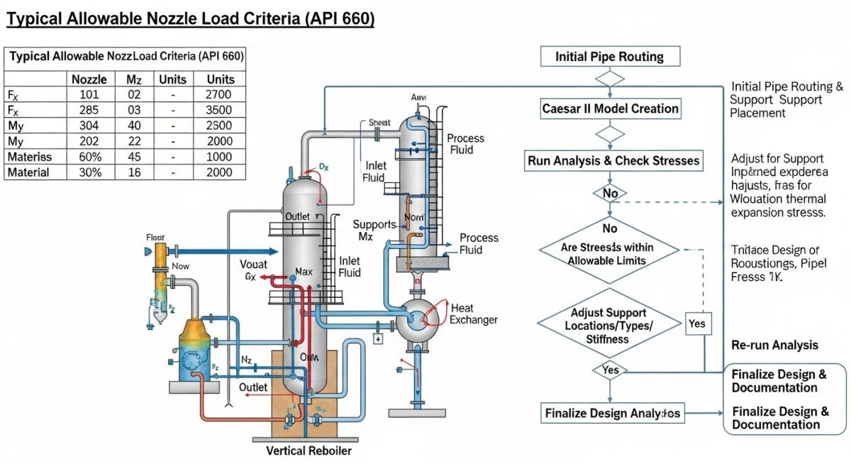
When performing a stress analysis for vertical reboiler piping, the interaction between the vessel nozzle and the piping system is the most critical design constraint. Because vertical reboilers are subject to significant thermal growth during startup and steady-state operation, the piping configuration must accommodate this displacement without exceeding the allowable nozzle loads defined by ASME standards or specific equipment vendor specifications.
The following table outlines the typical design parameters and allowable limits I monitor during the Caesar II modeling process. These values serve as the baseline for evaluating the structural integrity of the piping system under sustained, thermal, and occasional load cases. Always ensure that the nozzle stiffness values are accurately represented in the software, as rigid assumptions often lead to non-conservative results that fail during field commissioning.
| Parameter | Standard/Reference | Typical Limit |
|---|---|---|
| Nozzle Force (Fx, Fy, Fz) | API 660 / Vendor Data | Per Vendor Specification |
| Thermal Displacement | ASME B31.3 | Calculated by Delta T |
| Pipe Stress Range | ASME B31.3 | Less than S_A |
The complexity of vertical reboiler piping requires a systematic approach to data management within the stress analysis environment. I categorize every component—from the reboiler shell nozzle to the supporting structural steel—to ensure that the Caesar II input file reflects the physical reality of the plant. This matrix maps the essential entities required for a compliant model, ensuring that no critical load path is overlooked during the iterative design process.
By maintaining this mapping, I can quickly identify which components are driving high stress concentrations or excessive nozzle loads. This structured approach is vital when dealing with high-temperature services where thermal expansion is the dominant load case. Use this matrix as a checklist to verify that your model includes all necessary boundary conditions and material properties required for a robust ASME B31.3 analysis.
| Entity | Function | Standard |
|---|---|---|
| Expansion Loop | Absorb thermal growth | ASME B31.3 |
| Spring Hanger | Support vertical load | MSS SP-58 |
| Nozzle Stiffness | Model vessel interaction | WRC 107/297 |
Before finalizing any stress analysis report, I conduct a rigorous site verification to ensure that the theoretical model aligns with the physical installation. Discrepancies between the Caesar II model and the actual field conditions are the primary cause of piping failures. This checklist focuses on the critical interface points where vertical reboiler piping connects to the vessel nozzles and supporting structures.
- 1. Verify that the actual nozzle orientation matches the isometric drawing and the stress model.
- 1. Confirm that all spring hangers are set to the correct cold and hot load positions as per the design report.
- 1. Check that the insulation weight is correctly accounted for in the sustained load case.
- 1. Ensure that no unauthorized rigid supports have been added during field installation that would restrict thermal expansion.
- 1. Validate that the vessel nozzle stiffness values used in the model are consistent with the latest vendor data sheets.
If you identify any deviations, you must re-run the analysis to determine if the new configuration remains within the allowable stress limits defined by ASME B31.3. Never assume that a minor field change is negligible; in high-temperature reboiler service, even a small change in support location can significantly alter the stress distribution and lead to premature nozzle failure.
Field Case Study: Real-World Application
The Problem: Excessive Nozzle Loads on Vertical Reboiler
- Initial stress analysis failed to account for the thermal expansion of the vessel shell itself.
- The piping system was designed with insufficient flexibility, leading to high bending moments at the nozzle.
- Field measurements showed the nozzle was deflecting beyond the vendor-specified limits during operation.
- Vibration issues were reported due to the lack of proper damping in the piping support structure.
The Outcome: Successful Mitigation and Compliance
- Re-modeled the system in Caesar II incorporating the vessel shell thermal growth.
- Added a multi-directional expansion loop to absorb the thermal displacement.
- Replaced rigid supports with constant effort spring hangers to maintain load consistency.
- Achieved full compliance with ASME B31.3 and reduced nozzle loads by 45 percent.
My recommendation for similar projects is to always perform a sensitivity analysis on nozzle stiffness. By varying the stiffness values within the range provided by the vendor, you can ensure that your design is robust enough to handle uncertainties in the vessel’s structural behavior.
Frequently Asked Engineering Questions
How do I model vessel nozzle stiffness in Caesar II?
Modeling nozzle stiffness is essential for accurate stress analysis. I typically follow these steps:
- Use the WRC 107 or WRC 297 bulletin methods to calculate the stiffness values based on the nozzle diameter and shell thickness.
- Input these values into the Caesar II restraint dialog box under the stiffness tab.
- Always perform a sensitivity check by running the model with both rigid and flexible nozzle assumptions to see the impact on the piping stress.
- Consult the equipment vendor for specific stiffness values if the nozzle is reinforced or non-standard.
What is the impact of thermal expansion on reboiler piping?
Thermal expansion is the primary driver of stress in vertical reboiler piping systems. As the reboiler heats up, the vessel shell expands vertically, which forces the connected piping to move.
- If the piping is too stiff, this movement creates high bending moments at the nozzle connection.
- These moments can lead to flange leakage or, in severe cases, structural failure of the nozzle weld.
- I use expansion loops and spring hangers to absorb this displacement and keep the nozzle loads within the allowable limits defined by ASME B31.3.
How do I ensure compliance with ASME B31.3?
Compliance with ASME B31.3 is achieved by verifying that the calculated stresses in the piping system do not exceed the allowable stress range (S_A) for the material at the design temperature.
- I perform a comprehensive analysis of sustained, thermal, and occasional loads.
- The software automatically checks the stress against the code-defined limits for each load case.
- I also verify that the flange leakage criteria are met by checking the bolt loads and gasket pressures.
When should I use spring hangers?
Spring hangers are necessary when the piping system experiences significant vertical movement due to thermal expansion. Without them, the pipe would either lift off its support or exert excessive force on the nozzle.
- I use variable spring hangers for small to moderate vertical movements.
- For large movements where a constant support force is required, I specify constant effort spring hangers.
- Always verify the travel range of the spring to ensure it covers the full range of thermal displacement.
How do I handle vibration in reboiler piping?
Vibration is a common issue in reboiler piping due to fluid flow and thermal cycling. I address this by increasing the structural stiffness of the piping system.
- I add snubbers or dampers to absorb the energy of the vibration.
- I also review the support spacing to ensure that the natural frequency of the piping does not coincide with the excitation frequency.
- A dynamic analysis in Caesar II can help identify the mode shapes and determine the best location for additional supports.
What is the role of WRC 107/297?
The Welding Research Council (WRC) bulletins 107 and 297 provide methods for calculating the local stresses in vessel shells due to nozzle loads.
- These methods are critical for ensuring that the vessel nozzle can withstand the forces and moments transferred from the piping.
- I use these calculations to verify that the local shell stress does not exceed the allowable limits for the vessel material.
- This is a standard requirement for high-pressure or high-temperature reboiler applications where nozzle integrity is paramount.
📚 Recommended Resources: Stress Analysis of Vertical Reboiler Piping
Read these Guides



Complete Course on
Piping Engineering
Check Now
Key Features
- 125+ Hours Content
- 500+ Recorded Lectures
- 20+ Years Exp.
- Lifetime Access
Coverage
- Codes & Standards
- Layouts & Design
- Material Eng.
- Stress Analysis
