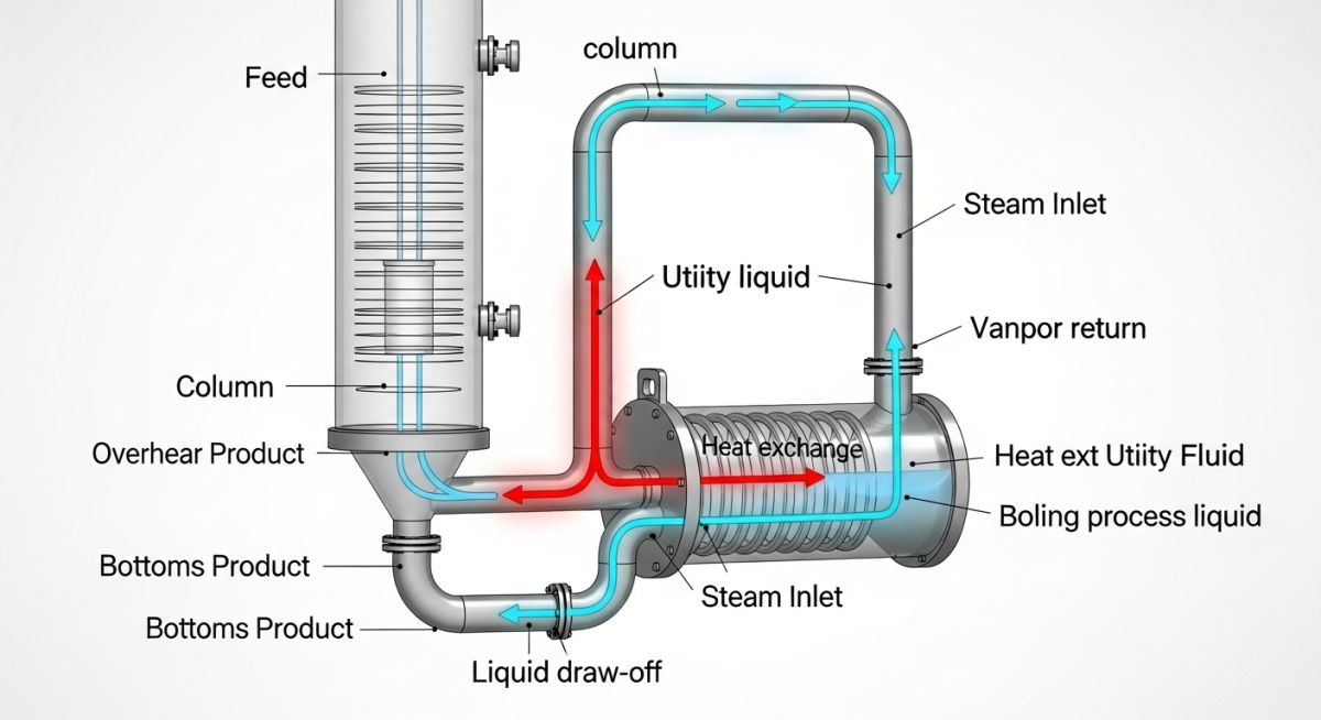
What is a Reboiler? Types and Selection of Reboilers
In my 20 years of designing piping systems and heat transfer equipment for global petrochemical plants, I have seen many engineers treat reboilers as simple utility heaters. This is a costly mistake. A reboiler is the beating heart of a distillation column. If your reboiler underperforms, your entire separation process stalls, leading to off-spec products and massive energy losses.
When we design these systems, we must balance complex fluid dynamics, phase change thermodynamics, and thermal expansion stresses. Selecting the wrong configuration can lead to severe operational headaches like column flooding, rapid fouling, or destructive flow oscillations. Let us dive deep into the engineering realities of these critical heat exchangers.
Key Engineering Takeaways
- Understand how vapor-liquid equilibrium (VLE) dictates reboiler thermal design.
- Identify the mechanical and process boundaries of Kettle, Thermosyphon, and Forced Circulation configurations.
- Master the hydraulic balance calculations required to prevent flow instability.
- Learn how to apply TEMA standards to minimize fouling and mechanical failure.
- Implement robust piping layouts that accommodate high thermal expansion without overloading equipment nozzles.
How to Master Reboiler Types and Selection
To select the right reboiler, you must first understand the physical mechanisms of boiling. We primarily deal with two boiling regimes in industrial practice: nucleate boiling and film boiling. Our goal is almost always to operate safely within the nucleate boiling regime, where heat transfer coefficients are high. If the heat flux exceeds the critical limit, a vapor film forms on the tube surface (film boiling), causing heat transfer rates to plummet and tube temperatures to spike.
1. Kettle Reboilers (TEMA K-Shell)
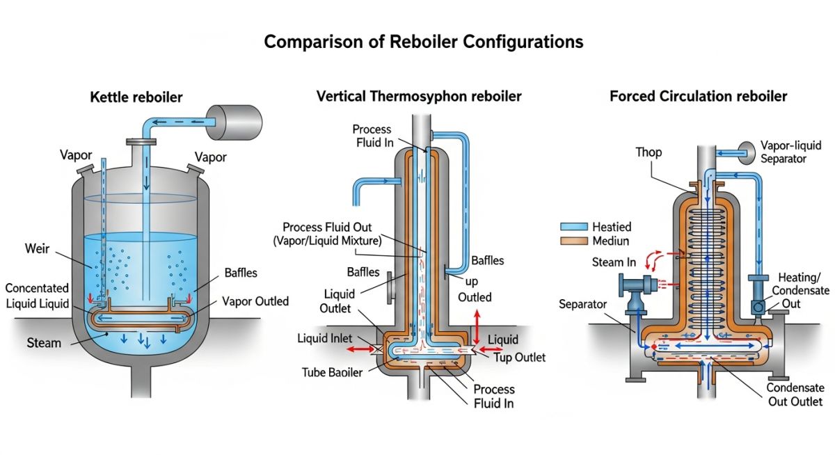
Kettle reboilers are incredibly reliable and simple to operate. They consist of a bundle of tubes submerged in a large pool of boiling liquid inside an oversized shell (the K-shell). The liquid from the column bottom enters the shell, and vapor flows back to the column from the top of the shell.
- Vapor-Liquid Separation: The large vapor space above the liquid pool allows entrained liquid droplets to settle out, delivering high-quality vapor back to the column.
- Weir Design: An internal weir maintains a constant liquid level over the tube bundle. The heavy, non-volatile residue overflows the weir into a discharge chamber, where it is drawn off as bottom product.
- Limitations: They have a high residence time, making them unsuitable for thermally sensitive fluids. They also require a large plot footprint and are expensive due to the oversized shell.
2. Thermosyphon Reboilers
Thermosyphons rely on natural density differences to circulate fluid through the exchanger. As the fluid inside the tubes heats up and begins to vaporize, its density decreases. The heavier column of cold liquid in the distillation column sump pushes the lighter, two-phase mixture up and out of the reboiler.
- Vertical Thermosyphons: Typically mounted directly to the side of the column. The process fluid passes through the tube side in a single pass, which yields very high heat transfer coefficients and low residence times. However, they require significant vertical clearance and structural support.
- Horizontal Thermosyphons: The process fluid flows on the shell side. They are easier to maintain because the tube bundle can be pulled without dismantling the entire structure, but their hydraulic calculations are more complex.
3. Forced Circulation Reboilers
When dealing with highly viscous, heavily fouling, or slurry-laden process streams, natural circulation is out of the question. Here, we use a forced circulation reboiler. A dedicated centrifugal pump forces the liquid through the heat exchanger tubes at high velocities (typically 1.5 to 3.0 meters per second).
The high velocity suppresses boiling inside the tubes by increasing the static head, keeping the fluid in the liquid phase until it passes through a restriction orifice into the column flash space. This design drastically reduces fouling but comes with high capital costs for the pump and high ongoing utility costs for electrical power.
Fundamental Design Calculations
To size a reboiler, we must calculate the required heat transfer area using the fundamental heat transfer equation:
Where:
- Q: Heat duty required to vaporize the target flow rate (Watts or BTU/hr).
- U: Overall heat transfer coefficient (W/m²·K or BTU/hr·ft²·°F), which accounts for tube-side and shell-side film coefficients, tube wall resistance, and fouling factors.
- A: Required heat transfer area (m² or ft²).
- LMTD: Logarithmic Mean Temperature Difference between the heating medium (e.g., steam, hot oil) and the boiling process fluid.
For thermosyphons, we must also calculate the Circulation Ratio (CR), which is the ratio of the total mass flow rate entering the reboiler to the mass flow rate of the vapor generated:
In my practice, I always target a CR between 3:1 and 10:1. If the CR is too low (less than 3:1), the high vapor fraction inside the tubes can cause localized dry-out, leading to rapid fouling and tube failure.
All mechanical designs must strictly comply with ASME Section VIII Division 1 for pressure vessel safety and TEMA Standards for shell and tube mechanical configurations.
The table below provides a direct comparison of the primary reboiler configurations used in modern chemical processing plants. Use this matrix during the conceptual design phase to narrow down your options based on process fluid characteristics and plot constraints.
| Reboiler Type | Fouling Resistance | Relative Cost | Plot Space Required | Typical Applications |
|---|---|---|---|---|
| Kettle (TEMA K) | Moderate to Low | High | Large (Horizontal) | Clean fluids, high vaporization rates, vacuum systems |
| Vertical Thermosyphon | Moderate | Low to Medium | Minimal (Vertical) | Low-viscosity fluids, moderate pressure, low fouling |
| Horizontal Thermosyphon | Moderate | Medium | Medium (Horizontal) | Large duties, clean hydrocarbons, narrow boiling ranges |
| Forced Circulation | Very High | Very High | Large (Requires Pump) | Slurries, highly viscous fluids, severe fouling services |
This technical mapping links key design parameters to their governing industry standards. Ensure your engineering data sheets reference these codes during the procurement phase.
| Design Parameter | Governing Standard | Critical Limit / Range | Engineering Significance |
|---|---|---|---|
| Mechanical Integrity | ASME Sec VIII Div 1 | Full Vacuum to 300+ bar | Prevents catastrophic pressure boundary failures |
| Shell & Tube Tolerances | TEMA Class R / C / B | Class R for severe refinery duty | Defines corrosion allowances and tube layouts |
| Piping Stress Limits | ASME B31.3 | Allowable displacement stress | Protects reboiler nozzles from thermal expansion loads |
| Fouling Allowances | API Standard 660 | 0.001 to 0.004 hr·ft²·°F/BTU | Ensures the exchanger can meet duty at end-of-run |
Field Verification for Reboiler Installation Success
Before you sign off on a reboiler installation, you must perform a rigorous field walkdown. Thermal expansion is the single biggest killer of reboiler nozzles. Because these units operate at high temperatures, the piping expands significantly. If the piping design does not incorporate adequate flexibility, the resulting forces will crack the reboiler nozzles or distort the shell.
Pre-Commissioning Inspection Protocol
-
Nozzle Load Verification: Confirm that the final piping alignment does not impose cold-spring forces on the reboiler nozzles. Check the stress analysis report against actual field support locations.
-
Sliding Saddle Clearance: Ensure that the bolts on the sliding saddle support of horizontal reboilers are not fully tightened. They must have a gap (typically 1.5 to 2 mm) to allow the vessel to expand thermally.
-
Thermosyphon Driving Head: Verify that the elevation difference between the column bottom liquid level and the reboiler centerline matches the hydraulic datasheet within a tolerance of +/- 25 mm.
-
Venting and Draining: Confirm that high-point vents and low-point drains are installed on both the shell and tube sides to facilitate complete purging and steaming out during maintenance.
-
Steam Trap Sizing and Piping: For steam-heated reboilers, verify that the condensate outlet piping drops vertically into a properly sized steam trap or condensate recovery system to prevent condensate water-hammer.
Field Case Study: Real-World Application
The Problem: Severe Fouling and Column Flooding
At a refinery in Texas, a vertical thermosyphon reboiler handling heavy gas oil was experiencing severe fouling within 45 days of operation. The heat transfer coefficient dropped by 60%, forcing the operators to increase the heating steam pressure. This increased the tube wall temperature, which accelerated coking inside the tubes.
Eventually, the system suffered from severe flow oscillations, causing liquid carryover and column flooding. The plant was losing approximately 120,000 per day in off-spec product and downtime.
The Outcome: Redesign and Hydraulic Optimization
I was called in to lead the troubleshooting team. Our hydraulic analysis revealed that the static head in the column was insufficient to maintain the required circulation ratio. The fluid was vaporizing too early in the tubes, leading to localized dry-out and coking.
We executed two major modifications:
- We raised the column liquid level setpoint by 1.2 meters to increase the driving static head.
- We replaced the standard tube bundle with one featuring a modified pitch and inserted high-efficiency turbulators to increase fluid velocity and shear stress at the tube wall.
These changes increased the circulation ratio from 2.1:1 to 5.4:1. The fouling rate dropped dramatically, extending the run-length from 45 days to over 18 months without a single unscheduled shutdown.
Direct Recommendation: Never design a thermosyphon reboiler without performing a dynamic simulation of the entire loop, including the column sump, the exchanger, and the return piping. Small errors in static head calculations lead to massive operational failures.
FAQs on Reboiler Types and Selection
What is the primary difference between a kettle reboiler and a thermosyphon reboiler?
When should I select a forced circulation reboiler over a thermosyphon?
How does the circulation ratio affect thermosyphon performance?
Why is piping flexibility so critical in reboiler design?
What is the purpose of the weir in a kettle reboiler?
Which TEMA shell types are most commonly used for reboilers?
Complete Course on
Piping Engineering
Check Now
Key Features
- 125+ Hours Content
- 500+ Recorded Lectures
- 20+ Years Exp.
- Lifetime Access
Coverage
- Codes & Standards
- Layouts & Design
- Material Eng.
- Stress Analysis