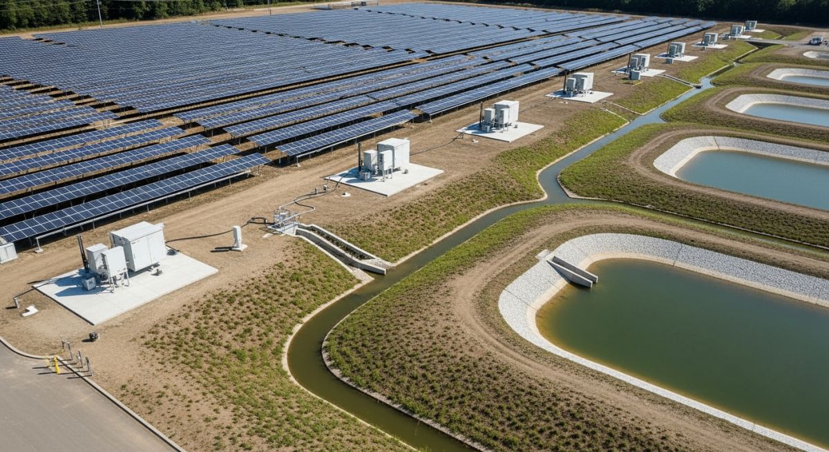
Flood Risk Assessment for Solar Farms: Engineering Design Guide
In my two decades of experience managing large-scale utility projects, I have observed that the most common failure point for solar assets is not electrical, but hydrological. A robust Flood Risk Assessment for Solar Farms is not merely a regulatory checkbox; it is the primary defense mechanism for your capital investment. When we design these sites, we must account for the altered runoff coefficients caused by thousands of impervious PV modules, which can drastically change the local watershed dynamics.
This guide provides the technical framework for evaluating site-specific flood hazards, calculating design flood elevations, and implementing mitigation strategies that satisfy both local permitting authorities and project financiers. We will move beyond basic site grading to explore how hydraulic modeling and structural elevation requirements dictate the long-term viability of your solar array.
Key Engineering Takeaways:
- Integration of ASCE 24-14 standards for flood-resistant design.
- Hydraulic modeling requirements for post-development runoff analysis.
- Strategic site grading to minimize scour and erosion at racking foundations.
- Regulatory compliance pathways for sites within Special Flood Hazard Areas (SFHA).
Technical Analysis: Flood Risk Assessment for Solar Farms
Flood Risk Assessment for Solar Farms: The quantitative process of determining the Base Flood Elevation (BFE) and potential flow velocities to establish minimum finished floor or equipment elevations for sensitive electrical components.
When performing a Flood Risk Assessment for Solar Farms, the engineer must first establish the hydrologic baseline. We utilize the Rational Method for smaller catchments or the SCS Curve Number method for larger, complex watersheds to determine peak discharge rates. The introduction of solar arrays changes the site’s surface characteristics; while the ground remains permeable, the concentrated runoff from panel edges creates “drip lines” that can lead to localized erosion if not managed through strategic site grading and vegetation stabilization.
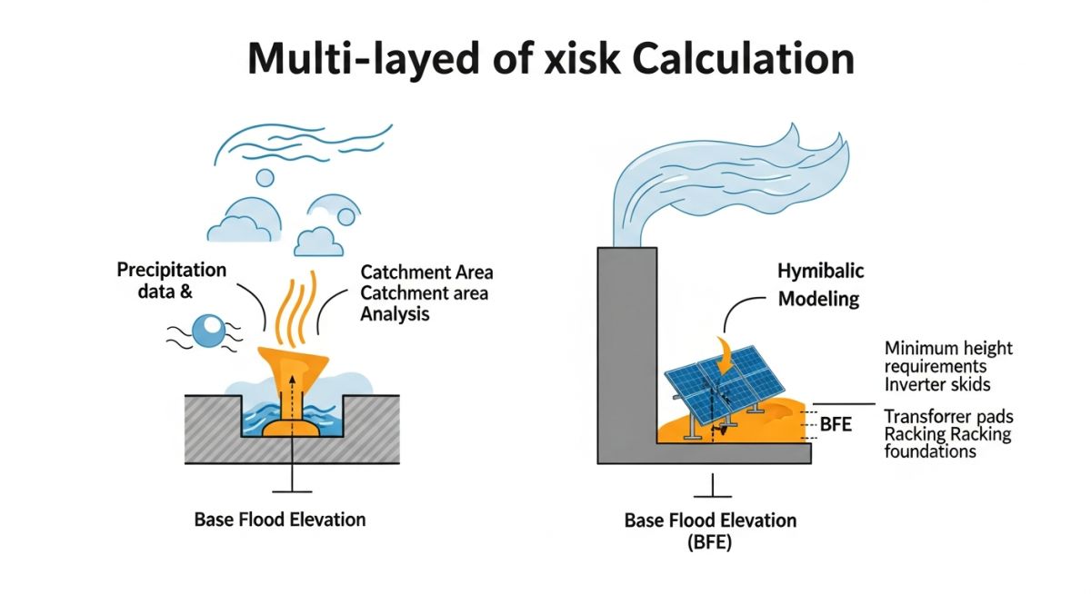
The core of the assessment relies on the FEMA Flood Insurance Rate Maps (FIRM). If the site falls within an A-Zone or AE-Zone, we must calculate the Design Flood Elevation (DFE), which is typically the BFE plus a factor of safety known as “freeboard.” In my experience, a minimum of 12 to 24 inches of freeboard is standard practice to account for climate-induced changes in precipitation intensity that may not be reflected in historical data.
Field Warning: Scour and Foundation Stability
High-velocity floodwaters can induce scour around pile-driven foundations. During the assessment, you must calculate the potential scour depth using the HEC-18 methodology. If the calculated scour depth exceeds the embedment depth of the racking piles, the structural integrity of the entire array is compromised, regardless of the electrical equipment’s elevation.
Hydraulic modeling software such as HEC-RAS is essential for simulating 100-year and 500-year storm events. We input the site’s topography, Manning’s roughness coefficients (n-values), and boundary conditions to map the flood extent. The goal is to ensure that the solar racking and inverters are positioned outside the high-velocity flow paths. If the site is constrained, we implement compensatory storage—excavating soil in one area to offset the volume displaced by structural fill or equipment pads—to ensure no net increase in flood stage for downstream properties.
Finally, we must address the electrical infrastructure. Inverters and transformers are the most vulnerable components. Per NFPA 70 (National Electrical Code), these must be protected from water ingress. I recommend elevating these units on concrete piers or reinforced pads at least 1 foot above the DFE. This elevation strategy, combined with robust site drainage, forms the backbone of a resilient solar project design.
Flood Mitigation Trade-offs: A technical evaluation of the structural and financial implications of implementing flood-resilient design measures in utility-scale solar developments.
Advantages
- Asset Longevity: Elevating critical electrical components significantly reduces the risk of catastrophic failure during extreme weather events.
- Regulatory Approval: Proactive flood modeling facilitates faster permitting by demonstrating no adverse impact on the surrounding watershed.
- Insurance Premiums: Documented flood risk mitigation often leads to lower insurance premiums and better terms from project lenders.
- Operational Continuity: Minimized site inundation ensures that maintenance crews can access the site immediately following a storm event.
Disadvantages
- Increased CAPEX: Significant site grading, compensatory storage excavation, and elevated equipment pads increase initial construction costs.
- Geotechnical Complexity: Deeper pile embedment required to resist scour forces can increase foundation material and installation labor costs.
- Environmental Permitting: Extensive grading or excavation in floodplains may trigger additional environmental impact studies or wetland mitigation requirements.
- Maintenance Burden: Engineered drainage systems, such as detention basins and swales, require ongoing inspection and sediment removal to remain effective.
Flood Resilience Implementation: Strategic deployment of hydraulic engineering principles across diverse solar project environments to ensure long-term structural and operational stability.
Utility-Scale Solar in Riverine Floodplains
In projects located near major river systems, we utilize detailed HEC-RAS modeling to define the floodway and flood fringe. By aligning the rows of solar panels parallel to the direction of flood flow, we minimize the drag coefficient and reduce the lateral force exerted on the racking structures during a flood event.
Brownfield Solar Redevelopment
Redeveloping former industrial sites often involves complex drainage patterns and existing subsurface infrastructure. Our flood assessment focuses on managing runoff to prevent the mobilization of legacy contaminants, using lined detention basins to ensure that site drainage does not interact with potentially hazardous soil layers.
Coastal Solar Array Protection
For solar farms in coastal regions, the assessment must account for storm surge and sea-level rise projections. We implement elevated inverter platforms and corrosion-resistant foundation coatings to withstand both the hydrostatic pressure of floodwaters and the long-term exposure to saline environments.
When evaluating the hydrological integrity of a utility-scale solar facility, engineers must synthesize multiple data inputs to establish a robust design basis. The table below outlines the critical design parameters that dictate the selection of structural components, foundation depths, and site grading requirements. These values are derived from ASCE 7 and FEMA guidelines, ensuring that the solar array remains operational during extreme weather events.
It is imperative to note that these parameters are not static; they must be adjusted based on the specific return period of the flood event, typically the 100-year (1% annual chance) or 500-year (0.2% annual chance) flood. By aligning these variables with site-specific geotechnical reports, we minimize the risk of scour, buoyancy-induced foundation failure, and electrical equipment inundation.
| Parameter | Standard Reference | Design Impact |
|---|---|---|
| Base Flood Elevation (BFE) | FEMA FIRM | Determines minimum finished floor elevation for inverters. |
| Flow Velocity (V) | ASCE 24 | Governs scour protection requirements for pile foundations. |
| Hydrostatic Pressure | ASCE 7-22 | Calculates lateral load on tracker torque tubes. |
The integration of these parameters into the site civil design ensures that the facility meets local floodplain management ordinances. Failure to account for velocity-induced scour, in particular, often leads to premature structural degradation of the racking system.
The following matrix maps the core technical entities involved in a comprehensive flood risk assessment for solar farms. By categorizing these components, we establish a clear hierarchy of responsibility between the civil, structural, and electrical engineering disciplines. This mapping is essential for maintaining compliance with international standards and local regulatory frameworks.
Each entity listed below represents a critical node in the project lifecycle, from initial site feasibility studies to final commissioning. Understanding the interaction between these entities allows for more accurate modeling of flood-related risks and the subsequent implementation of effective mitigation strategies.
| Entity | Acronym | Primary Standard |
|---|---|---|
| Flood Insurance Rate Map | FIRM | FEMA |
| Flood Damage-Resistant Design | FDRD | ASCE 24 |
| Hydraulic Modeling Software | HEC-RAS | USACE |
Utilizing these standardized entities ensures that all stakeholders, including permitting agencies and insurance underwriters, operate from a unified technical vocabulary. This consistency is vital for project bankability and long-term asset protection.
Performing a rigorous site verification is the final safeguard against unforeseen hydrological impacts. In my experience, the difference between a resilient solar farm and a catastrophic failure often lies in the attention paid to these granular site details during the pre-construction phase.
-
01.
Verify that all inverter pads are elevated at least 12 inches above the 100-year Base Flood Elevation (BFE) per ASCE 24. -
02.
Confirm that the site grading plan accounts for post-development runoff coefficients to prevent localized ponding near tracker drive motors. -
03.
Inspect all pile foundation depths to ensure they extend below the calculated scour depth for the 100-year flood event. -
04.
Validate that all electrical conduits and cable trenches are sealed against water ingress, utilizing NEMA 4X rated enclosures where necessary. -
05.
Review the emergency access road design to ensure it remains passable during a 25-year storm event for maintenance and safety personnel.
Each item on this checklist must be signed off by the lead civil engineer. If any item fails verification, the design must be revisited to incorporate additional drainage capacity or structural reinforcement. Remember, the goal is to maintain the integrity of the electrical system while minimizing the environmental impact of the site development on the surrounding watershed.
Problem: Inadequate Scour Protection in a Floodplain Solar Project
- The project was sited in a low-lying area adjacent to a seasonal creek, where the 100-year flood event was underestimated.
- Initial pile foundation designs did not account for the high-velocity flow during peak flood stages, leading to significant soil erosion around the posts.
- The lack of rip-rap or vegetative stabilization resulted in the loss of lateral support for the racking system, causing structural tilting.
- Electrical cable trenches were not properly backfilled with non-erodible material, leading to exposed wiring and potential ground faults.
Outcome: Successful Remediation and Future-Proofing
- Implemented a comprehensive scour protection plan using geotextile fabric and stone armoring around all critical foundation piles.
- Regraded the site to direct high-velocity flows away from the primary inverter blocks, utilizing bioswales to manage runoff.
- Increased the embedment depth of the piles by 30% to compensate for potential soil loss during extreme weather events.
- Established a long-term monitoring program to track soil stability and vegetation growth, ensuring the site remains within the design parameters.
My recommendation for future projects is to prioritize a detailed hydraulic analysis early in the development phase. Do not rely solely on regional flood maps; perform site-specific modeling to account for the unique topography and drainage characteristics of your specific project location.
How does ASCE 24 influence solar farm design?
ASCE 24 provides the minimum requirements for flood-resistant design and construction of structures in flood hazard areas. For solar farms, it dictates the following:
- Mandates that critical electrical equipment, such as inverters and transformers, be elevated above the Design Flood Elevation (DFE).
- Requires that structural components be designed to withstand hydrostatic and hydrodynamic loads, including the impact of floating debris.
- Ensures that the site grading does not increase the flood risk to adjacent properties, a key requirement for local permitting.
What is the role of HEC-RAS in flood modeling?
HEC-RAS is the industry-standard software for performing one-dimensional and two-dimensional hydraulic calculations. In solar engineering, it is used to:
- Model the water surface profile across the site during various storm return periods.
- Calculate the velocity of floodwaters, which is essential for determining the required scour protection for pile foundations.
- Simulate the impact of proposed site grading and access roads on the natural flow of water through the floodplain.
How do I calculate scour depth for piles?
Scour depth calculation is a critical step in ensuring the long-term stability of the solar racking system. The process involves:
- Determining the flow velocity and depth from the hydraulic model.
- Applying empirical formulas, such as the Richardson and Davis method, to estimate the local scour depth around the pile.
- Adding a factor of safety to account for soil variability and potential long-term degradation of the riverbed.
Are there specific requirements for cable trenches?
Yes, cable trenches in flood-prone areas require special attention to prevent water damage and soil erosion. Key considerations include:
- Using non-erodible backfill materials, such as crushed stone or concrete, in areas subject to high-velocity flow.
- Ensuring that all conduit entries into equipment pads are sealed with water-tight fittings.
- Designing the trench layout to avoid acting as a preferential flow path for surface water, which could lead to internal erosion.
How does site grading affect flood risk?
Site grading is the primary tool for managing flood risk at the project level. Effective grading strategies include:
- Creating positive drainage away from critical infrastructure to prevent ponding.
- Utilizing detention basins to manage the increase in runoff caused by the installation of impervious surfaces like inverter pads.
- Maintaining natural drainage patterns to ensure that the site does not impede the flow of water through the floodplain.
What is the importance of the 100-year flood?
The 100-year flood, or the 1% annual chance flood, serves as the regulatory benchmark for floodplain management. Its importance lies in:
- Establishing the Base Flood Elevation (BFE) used for insurance and permitting purposes.
- Defining the minimum design requirements for structures located within the Special Flood Hazard Area (SFHA).
- Providing a standardized risk metric that allows engineers and developers to communicate the potential impact of flood events to stakeholders.
Complete Course on
Piping Engineering
Check Now
Key Features
- 125+ Hours Content
- 500+ Recorded Lectures
- 20+ Years Exp.
- Lifetime Access
Coverage
- Codes & Standards
- Layouts & Design
- Material Eng.
- Stress Analysis
