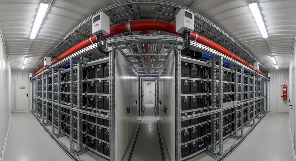
BESS Thermal Runaway: Engineering Safety and Mitigation Strategies
In my two decades of experience designing complex industrial piping and energy infrastructure, I have observed that the rapid scaling of Battery Energy Storage Systems (BESS) introduces unprecedented fire safety challenges. Thermal runaway is not merely a battery defect; it is a complex, self-sustaining exothermic reaction that can propagate through an entire rack if not managed by robust engineering controls.
As engineers, we must move beyond basic fire codes and integrate multi-layered protection strategies. This article explores the technical nuances of cell-level monitoring, off-gas detection, and the critical role of suppression systems in preventing catastrophic facility loss.
Key Takeaways for BESS Safety
- Implement early-stage off-gas detection to identify cell venting before thermal runaway occurs.
- Ensure compliance with NFPA 855 for spacing, fire rating, and ventilation requirements.
- Design suppression systems that account for the specific chemical composition of lithium-ion electrolytes.
- Prioritize passive containment and thermal barriers to prevent fire propagation between battery modules.
Engineering Analysis of BESS Thermal Runaway Mechanisms
Thermal Runaway Dynamics: The process of thermal runaway represents a critical failure mode where internal heat generation exceeds the heat dissipation capacity of the battery module, leading to a rapid, uncontrollable temperature rise.
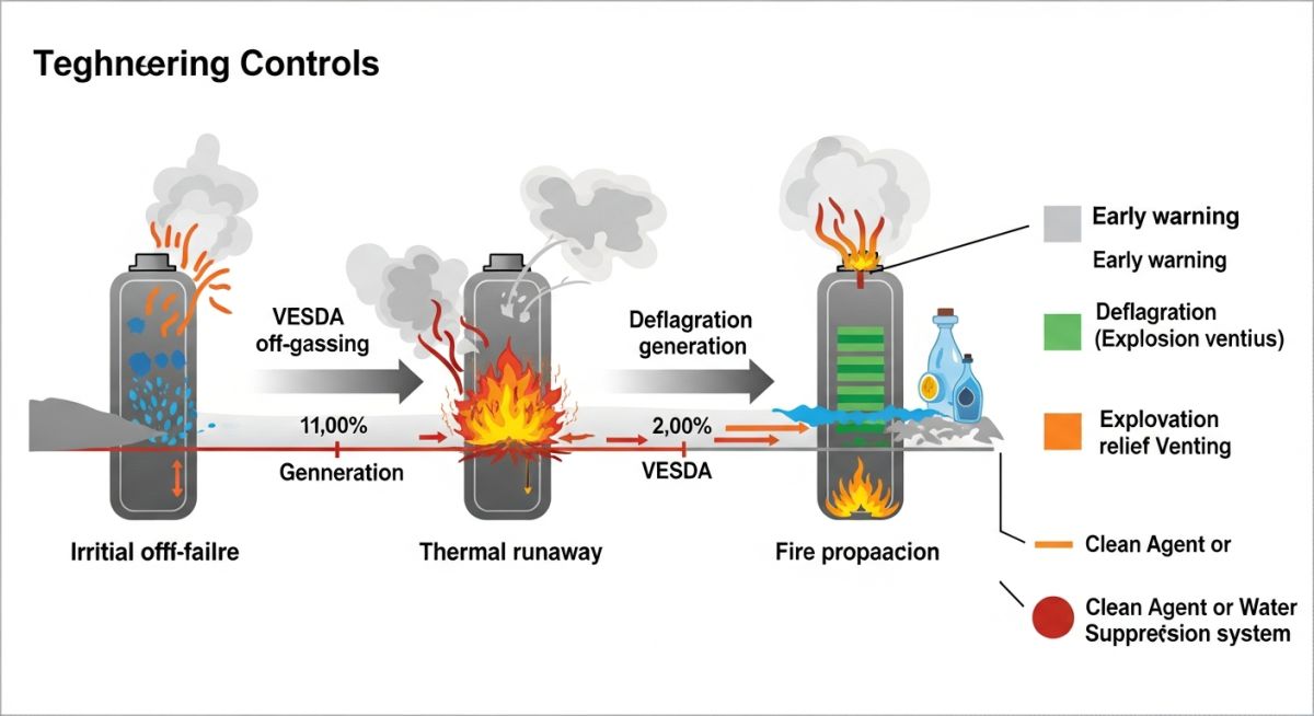
When a lithium-ion cell experiences an internal short circuit or mechanical abuse, the solid electrolyte interphase (SEI) layer begins to decompose at approximately 90 to 120 degrees Celsius. This decomposition is exothermic, releasing heat that triggers further reactions, including electrolyte oxidation and cathode decomposition. In my experience, the transition from localized heating to full-scale thermal runaway occurs in milliseconds, necessitating high-speed detection systems.
Quantifying Heat Release and Propagation
To design effective suppression, we must calculate the potential heat release rate (HRR). The total energy release is a function of the state of charge (SOC) and the total capacity of the battery bank. We utilize the following simplified energy balance equation for thermal stability:
Q_gen = Q_conv + Q_rad + Q_cond + Q_storage
Where Q_gen is the heat generated by chemical reactions, and the remaining terms represent the heat dissipation pathways. If Q_gen exceeds the sum of dissipation, the temperature increases exponentially. In large-scale BESS, we focus on limiting Q_gen through Battery Management Systems (BMS) that monitor voltage and temperature at the cell level.
Field Warning: The Propagation Risk
Propagation is the most significant risk in BESS design. If one cell enters thermal runaway, the heat transfer to adjacent cells can trigger a chain reaction. According to UL 9540A standards, testing must confirm that fire does not spread beyond the unit of origin. We mitigate this by installing thermal barriers and ensuring adequate spacing between racks to prevent radiant heat transfer.
Detection systems must be calibrated to detect off-gassing, which precedes thermal runaway by several minutes. By utilizing sensors that detect hydrogen, carbon monoxide, and volatile organic compounds (VOCs), we can initiate emergency ventilation or suppression before the cell reaches the critical temperature threshold. This proactive approach is the cornerstone of modern BESS safety engineering.
BESS Safety System Trade-offs: The selection of fire mitigation technologies involves balancing rapid response capabilities against the potential for secondary damage to sensitive electronic components.
Advantages of Advanced Suppression
- Early detection via off-gas sensors prevents full-scale thermal runaway.
- Water-based suppression systems provide superior cooling to stop propagation.
- Automated BMS integration allows for remote isolation of faulty battery strings.
- Compliance with NFPA 855 ensures insurability and regulatory approval.
Disadvantages and Technical Challenges
- High capital expenditure for multi-stage detection and suppression hardware.
- Water damage risk to non-affected battery modules during suppression activation.
- Complex maintenance requirements for high-sensitivity gas detection arrays.
- Potential for false positives leading to unnecessary system shutdowns.
BESS Deployment Scenarios: The application of thermal runaway mitigation strategies varies significantly based on the facility’s location, scale, and proximity to critical infrastructure.
Utility-Scale Grid Storage
Large-scale installations require robust fire-rated enclosures and high-capacity water deluge systems. These systems are designed to manage the massive energy density of containerized lithium-ion racks while ensuring that any thermal event is contained within the specific container unit.
Commercial and Industrial Microgrids
For facilities integrated into existing buildings, the focus shifts to gas detection and specialized ventilation. These systems must interface with building management systems to ensure that off-gassing is vented safely to the exterior, preventing toxic accumulation in occupied spaces.
Electric Vehicle Charging Hubs
High-power charging stations often utilize BESS to manage peak demand. Safety designs here prioritize rapid isolation of the battery storage from the charging infrastructure to prevent a single vehicle fire from escalating into a facility-wide storage failure.
Selecting the appropriate fire suppression system for a Battery Energy Storage System (BESS) requires a granular understanding of how different agents interact with lithium-ion cell chemistries. In my experience, the primary challenge is not just extinguishing the initial flame, but managing the deep-seated thermal energy that persists within the battery modules long after the surface fire is suppressed.
The following table outlines the performance characteristics of common suppression agents used in modern BESS facilities. Engineers must evaluate these against the specific energy density of the battery racks and the ventilation capacity of the enclosure. It is vital to remember that while water-based systems are highly effective for cooling, they require significant drainage management to prevent environmental contamination from electrolyte runoff.
| Suppression Agent | Primary Mechanism | Cooling Capacity | Standard Reference |
|---|---|---|---|
| Water Mist | Heat absorption and displacement | High | NFPA 750 |
| Clean Agents (FK-5-1-12) | Chemical flame inhibition | Low | NFPA 2001 |
| Aerosol Systems | Chain reaction interruption | Moderate | NFPA 2010 |
Always verify that the chosen suppression system is compatible with the specific BESS manufacturer’s warranty requirements, as some agents may leave residues that interfere with sensitive electronic monitoring equipment or battery management system (BMS) sensors.
The complexity of BESS safety design necessitates a structured approach to mapping physical hazards to regulatory requirements. This matrix serves as a technical bridge between the physical components of a BESS installation and the governing standards that dictate their safe operation and maintenance.
By aligning specific failure modes with their corresponding mitigation strategies, engineers can ensure that no critical safety layer is overlooked during the design phase. This mapping is particularly useful when conducting a Failure Mode and Effects Analysis (FMEA) for large-scale utility projects where the risk profile is significantly higher than in residential or commercial applications.
| Entity | Safety Function | Standard |
|---|---|---|
| BMS (Battery Management System) | Cell voltage and temperature monitoring | UL 1973 |
| Gas Detection | Early off-gas identification | NFPA 855 |
| Enclosure Integrity | Fire and explosion containment | UL 9540A |
Utilizing this matrix during the preliminary design review helps in identifying gaps in the safety architecture, ensuring that the BESS facility meets both local fire codes and international safety benchmarks for energy storage deployment.
Site verification is the final, critical step in ensuring that the BESS safety design is implemented as intended. My experience shows that even the most robust designs can fail if installation nuances—such as sensor placement or ventilation airflow—are not strictly validated against the original engineering specifications.
- Ventilation Verification: Confirm that the HVAC system provides the required air changes per hour (ACH) to prevent flammable gas accumulation as per NFPA 855.
- Sensor Calibration: Validate that all off-gas and smoke detection sensors are calibrated for the specific electrolyte decomposition products of the installed battery chemistry.
- Suppression Discharge Test: Ensure that the suppression system discharge pattern covers all battery racks without obstruction from cable trays or structural members.
- Emergency Egress: Verify that all personnel access points are clear of obstructions and that emergency lighting is operational during a total power loss scenario.
- BMS Integration: Confirm that the BMS is correctly interfaced with the fire alarm control panel (FACP) to trigger automatic shutdown upon detection of thermal runaway.
This checklist should be completed by a qualified commissioning agent. Any deviations from the design must be documented and re-evaluated through a formal Management of Change (MOC) process to ensure that the overall safety integrity level (SIL) of the facility remains uncompromised.
The Problem: Unexpected Thermal Runaway in a 5MW BESS Facility
- A single cell failure cascaded into a module-level thermal runaway event due to inadequate physical separation between battery racks.
- The existing smoke detection system failed to trigger early enough because it was not designed to detect the specific off-gassing precursors of the lithium-ion chemistry.
- Inadequate ventilation led to a rapid buildup of flammable gases, complicating the fire suppression efforts.
- The lack of a dedicated water-based cooling system meant that the fire suppression agent could not effectively remove the deep-seated heat from the battery modules.
The Outcome: Successful Mitigation and System Redesign
- Implemented a multi-stage detection system including off-gas sensors, which provided a 15-minute lead time over traditional smoke detectors.
- Installed high-capacity water mist suppression systems to provide both flame suppression and active cooling of the battery modules.
- Redesigned the rack layout to incorporate fire-rated barriers, effectively limiting the propagation of thermal runaway between adjacent modules.
- Updated the emergency response plan to include specific training for local fire departments on the unique hazards of lithium-ion energy storage systems.
This case study highlights the importance of a defense-in-depth approach. Relying on a single safety system is insufficient; a combination of early detection, physical containment, and active cooling is required to manage the risks inherent in large-scale energy storage.
Frequently Asked Engineering Questions
What is the primary purpose of UL 9540A testing?
The UL 9540A standard is designed to evaluate the fire propagation characteristics of BESS installations. It provides a standardized method to determine:
- Whether a thermal runaway event in a single cell will propagate to adjacent cells or modules.
- The composition and volume of flammable gases released during a failure.
- The effectiveness of the enclosure in containing the fire and preventing external damage.
How does NFPA 855 influence BESS design?
NFPA 855 serves as the comprehensive standard for the installation of stationary energy storage systems. It mandates specific requirements for:
- Fire suppression and detection system performance.
- Ventilation and explosion mitigation strategies.
- Separation distances between BESS units and other structures.
- Emergency planning and training for first responders.
Why is off-gas detection preferred over smoke detection?
Off-gas detection identifies the chemical precursors released during the initial stages of battery degradation, long before visible smoke or flames appear. This provides a critical window for the BMS to isolate the affected module, potentially preventing the thermal runaway event from escalating into a full-scale fire.
What role does the BMS play in fire safety?
The Battery Management System (BMS) is the primary active safety layer. It continuously monitors cell voltages and temperatures, executing automatic shutdown protocols if parameters exceed safe operating limits. It also communicates with the fire alarm system to initiate suppression if a thermal event is detected.
Are clean agents effective for BESS fires?
Clean agents are effective at suppressing surface flames but have limited cooling capacity. Because lithium-ion thermal runaway is a self-sustaining chemical reaction, clean agents alone are often insufficient. They are best used in combination with other systems that provide active cooling to the battery modules.
How should emergency responders approach a BESS fire?
Responders should prioritize site isolation and cooling. Key actions include:
- Establishing a safe perimeter due to the risk of explosion and toxic gas release.
- Using large volumes of water for cooling, while managing runoff.
- Consulting with on-site engineers to understand the specific BESS configuration and shutdown procedures.
Complete Course on
Piping Engineering
Check Now
Key Features
- 125+ Hours Content
- 500+ Recorded Lectures
- 20+ Years Exp.
- Lifetime Access
Coverage
- Codes & Standards
- Layouts & Design
- Material Eng.
- Stress Analysis

📚 Recommended Resources: BESS thermal runaway
Read these Guides
- 📄 BESS Integration with Solar Power Plants: Design and Operational Strategies
- 📄 BESS Sizing Calculations: Optimizing Battery Energy Storage System Capacity
- 📄 Engineering Utility-Scale BESS Plant Design: A Comprehensive Technical Guide
- 📄 Major Components of a BESS Plant: A Technical Engineering Overview