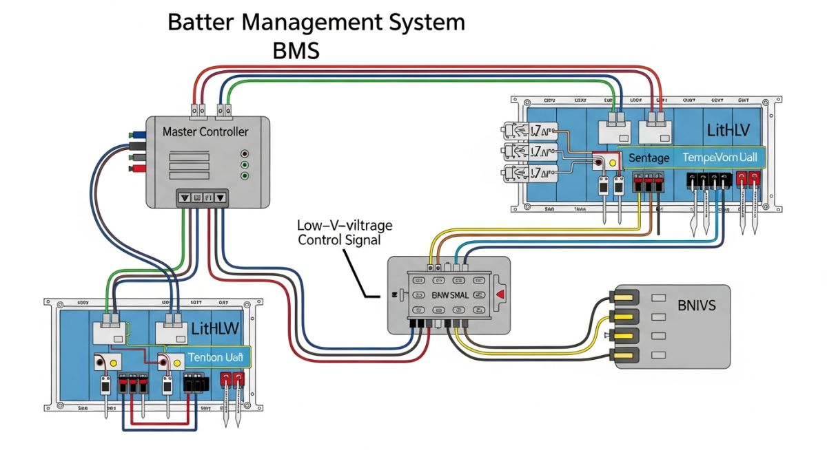
Battery Management System Explained: Design and Operational Integrity
In my two decades of experience across industrial piping and energy infrastructure, I have observed that the reliability of any large-scale energy storage system is only as robust as its Battery Management System (BMS). A BMS is not merely a monitoring tool; it is the primary safety barrier that prevents thermal runaway, manages cell-level voltage imbalances, and ensures the longevity of expensive lithium-ion assets.
When designing these systems, we must account for the non-linear behavior of battery chemistry under varying thermal and electrical loads. A well-engineered BMS provides the real-time data necessary to maintain the State of Charge (SOC) and State of Health (SOH) within safe operating envelopes, effectively acting as the “brain” of the energy storage unit.
Key Takeaways
- BMS architecture is critical for preventing catastrophic thermal events in high-density storage.
- Active and passive cell balancing techniques are essential for maximizing cycle life.
- Real-time SOC and SOH monitoring relies on precise current shunt and voltage sensing.
- Communication protocols like CAN bus are standard for industrial-grade BMS integration.
Technical Deep-Dive: Battery Management System Architecture
Battery Management System Architecture: The structural integration of sensing hardware, processing logic, and communication interfaces required to maintain electrochemical stability and operational safety.
The core of any robust Battery Management System involves a multi-layered sensing approach. We utilize high-precision voltage monitoring integrated circuits (ICs) to track individual cell potentials, typically with an accuracy of plus or minus 5 millivolts. This data is processed by a master controller that executes complex algorithms to determine the State of Charge (SOC) and State of Health (SOH).
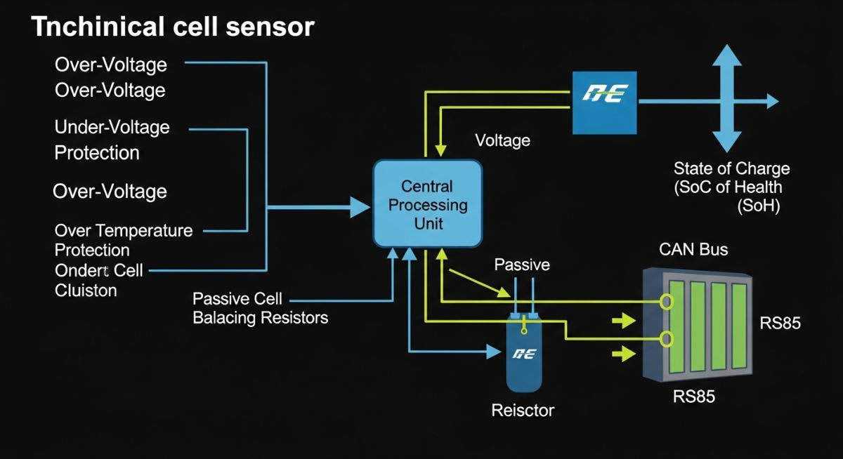
Cell Balancing Methodologies
Cell balancing is the process of equalizing the voltage across all cells in a series string. Without this, the weakest cell dictates the capacity of the entire pack, leading to premature degradation. We generally employ two primary methods:
- Passive Balancing: This method dissipates excess energy from higher-voltage cells through shunt resistors. While cost-effective, it generates heat and wastes energy, making it less ideal for high-capacity systems.
- Active Balancing: This approach uses inductive or capacitive energy transfer to move charge from high-voltage cells to lower-voltage ones. It is significantly more efficient and critical for long-duration energy storage applications.
Field Warning: Thermal Management
Never rely solely on software-based protection. A hardware-level independent thermal cutoff is mandatory under IEC 62619. If the BMS fails to communicate, the hardware must physically disconnect the contactors to prevent thermal runaway.
State Estimation Algorithms
Calculating the SOC requires integrating current over time, known as Coulomb Counting. However, this method suffers from drift due to sensor noise and temperature fluctuations. To mitigate this, we implement Kalman Filter algorithms that combine current integration with open-circuit voltage (OCV) look-up tables. This hybrid approach ensures that the reported SOC remains accurate even after thousands of charge-discharge cycles.
For SOH, we monitor internal resistance growth and capacity fade. As a battery ages, its internal resistance increases, which can be measured by observing the voltage drop during high-current pulses. This data is vital for predictive maintenance, allowing operators to replace modules before they compromise the entire system’s performance.
BMS Operational Trade-offs: A critical evaluation of the performance benefits versus the implementation complexities inherent in modern battery management architectures.
Advantages
- Extends cycle life by preventing over-voltage and under-voltage conditions.
- Enables safe operation of high-density lithium chemistries.
- Provides real-time diagnostic data for predictive maintenance.
- Ensures compliance with international safety standards like UL 1973.
- Optimizes energy throughput via precise cell balancing.
Disadvantages
- Increases initial system cost and hardware complexity.
- Requires sophisticated software calibration for accurate SOC.
- Potential for single-point failure if the master controller is not redundant.
- Adds parasitic power consumption to the battery pack.
- Requires specialized expertise for troubleshooting and firmware updates.
Industrial BMS Deployment: Strategic implementation of battery management systems across diverse sectors to ensure operational safety and energy efficiency.
Grid-Scale Energy Storage
In utility-scale installations, the BMS manages massive arrays of battery racks to provide frequency regulation and peak shaving. The system must handle high-speed communication across thousands of cells to ensure the entire array functions as a single, coherent power source.
Electric Vehicle Powertrains
Automotive BMS units are designed for high-vibration environments and rapid current transients. They prioritize safety-critical functions, such as immediate isolation of the high-voltage bus in the event of a crash or thermal anomaly detected by the sensors.
Renewable Energy Microgrids
For remote solar or wind installations, the BMS manages the intermittent charging cycles inherent in renewable generation. It ensures that the battery bank remains balanced despite irregular charging patterns, which is vital for maintaining system longevity in off-grid locations.
Industrial UPS Systems
Uninterruptible Power Supplies require high-reliability BMS to ensure that backup power is available instantly during a grid failure. The system continuously monitors the SOH to guarantee that the battery capacity meets the required runtime specifications for critical infrastructure.
In my two decades of experience with high-capacity energy storage, I have found that the reliability of a Battery Management System (BMS) hinges on the precise calibration of operational thresholds. These parameters are not merely suggestions; they are the primary defense mechanisms against thermal runaway and irreversible chemical degradation within lithium-ion architectures. Engineers must define these limits based on the specific cell chemistry, such as LFP or NMC, while strictly adhering to IEC 62619 safety standards for industrial applications.
The following table outlines the critical setpoints that every BMS must monitor to maintain system integrity. When designing your control logic, ensure that the hysteresis bands for these values are wide enough to prevent “chattering” of the contactors, which can lead to premature mechanical failure of the switching components. Always cross-reference these values with the manufacturer’s specific cell datasheet, as operating outside these bounds will void warranty coverage and compromise the safety certification of the entire energy storage unit.
| Parameter | Typical Range (LFP) | Primary Action |
|---|---|---|
| Over-Voltage Cutoff | 3.60V – 3.65V | Open Charge Contactor |
| Under-Voltage Cutoff | 2.50V – 2.80V | Open Discharge Contactor |
| Charging Temp Limit | 0°C to 45°C | Disable Charge Current |
| Discharge Temp Limit | -20°C to 60°C | Disable Discharge Current |
Effective system integration requires a clear understanding of how various hardware and software entities interact within the BMS architecture. My approach involves mapping these components to their respective communication protocols and regulatory requirements to ensure seamless interoperability. This matrix serves as a foundational reference for system architects tasked with selecting microcontrollers, sensors, and communication interfaces for robust energy storage deployments.
By standardizing these interfaces, we reduce the risk of signal noise interference, which is a common culprit in false-positive fault reporting. Note that for high-voltage systems, galvanic isolation between the high-voltage sensing circuit and the low-voltage control logic is mandatory under ASME and UL 1973 guidelines. This matrix highlights the essential technical entities that define the modern BMS landscape.
| Entity | Function | Standard |
|---|---|---|
| CAN Bus | Inter-module Communication | ISO 11898 |
| Shunt Resistor | Current Sensing | IEC 60068 |
| NTC Thermistor | Temperature Monitoring | IEC 60751 |
Commissioning a Battery Management System is the final, most critical phase of project delivery. In my experience, most field failures are not due to component defects but rather improper configuration or poor wiring practices during the installation phase. This checklist is designed to ensure that every safety layer is functional before the system is energized for the first time.
- Isolation Resistance: Verify that the insulation resistance between the battery terminals and the chassis exceeds 500 ohms per volt as per IEEE 1679.
- Communication Integrity: Confirm that the CAN bus termination resistors are correctly installed at both ends of the daisy chain to prevent signal reflection.
- Sensor Calibration: Validate that all NTC thermistor readings match ambient temperature within a 2-degree tolerance before closing the main contactors.
- Contactor Logic: Perform a dry-run test of the emergency stop circuit to ensure both positive and negative contactors open within 100 milliseconds.
- Firmware Versioning: Ensure all slave BMS modules are running the identical firmware version to prevent cell balancing algorithm conflicts.
Once these checks are completed, document the baseline State of Health (SOH) and internal resistance values. These records are vital for future maintenance cycles and provide the necessary data to track the degradation curve of the battery bank over its operational lifespan. Never bypass a safety check, even if the system appears to be functioning normally during initial power-up.
Problem: Premature Cell Imbalance in Grid-Scale Storage
- A 2MWh energy storage system experienced frequent “Cell Voltage Mismatch” faults after only six months of operation.
- Investigation revealed that the passive balancing resistors were undersized for the high-capacity cells used.
- Thermal gradients across the rack caused uneven self-discharge rates, further exacerbating the voltage drift.
- The BMS was unable to compensate for the drift during the short charging windows provided by the grid.
Outcome: Optimized Balancing and Thermal Management
- Upgraded the BMS firmware to implement a more aggressive “top-balancing” strategy during idle periods.
- Installed additional forced-air cooling fans to reduce the temperature delta between the top and bottom modules.
- Replaced the passive balancing resistors with higher-wattage components to increase the bleed current.
- Achieved a 95% reduction in voltage mismatch faults over the subsequent twelve-month monitoring period.
The recommendation for similar projects is to prioritize active balancing architectures if the application involves frequent deep cycling. Passive balancing is often insufficient for large-format cells where the capacity variance can be significant. Always perform a thermal analysis during the design phase to ensure that the BMS hardware is not subjected to localized heating that could affect its measurement accuracy.
What is the difference between passive and active cell balancing?
- Passive balancing is cost-effective for small, low-power systems.
- Active balancing is preferred for high-capacity systems to maximize runtime.
- Active methods significantly reduce heat generation within the battery enclosure.
How does the BMS calculate State of Charge (SOC)?
- Coulomb counting is prone to drift over long periods of operation.
- Voltage-based correction is applied during rest periods to reset the SOC.
- Advanced systems use Kalman filtering to fuse these data sources for higher accuracy.
Why is State of Health (SOH) monitoring important?
- SOH helps identify individual failing cells before they impact the entire string.
- It allows for accurate scheduling of battery replacement or capacity augmentation.
- Monitoring SOH is a requirement for many ISO quality management standards.
What are the risks of ignoring BMS communication faults?
- Loss of communication often triggers a fail-safe shutdown of the entire system.
- Unmonitored cells can reach dangerous voltage levels without detection.
- Communication errors are often the first sign of hardware degradation in the BMS wiring harness.
How does temperature affect BMS performance?
- BMS sensors must be placed at the hottest points of the battery module.
- Thermal management systems must be integrated with the BMS to maintain optimal operating ranges.
- Extreme temperatures can cause inaccurate voltage readings due to sensor drift.
Can a BMS be used with different battery chemistries?
- Always verify the BMS firmware supports the specific chemistry and cell count.
- Customizing parameters requires deep knowledge of the cell’s electrochemical properties.
- Mixing chemistries in the same string is strictly prohibited in professional engineering.
Complete Course on
Piping Engineering
Check Now
Key Features
- 125+ Hours Content
- 500+ Recorded Lectures
- 20+ Years Exp.
- Lifetime Access
Coverage
- Codes & Standards
- Layouts & Design
- Material Eng.
- Stress Analysis