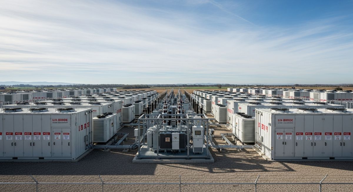
How Battery Energy Storage Systems Work: Engineering Fundamentals
In my two decades of managing complex industrial infrastructure, I have observed that the transition to renewable energy hinges entirely on our ability to master the physics of storage. A Battery Energy Storage System is not merely a collection of cells; it is a high-precision power plant that requires rigorous thermal management, bidirectional power conversion, and real-time software orchestration.
When we design these systems, we are balancing the delicate chemistry of lithium-ion or flow battery stacks against the harsh realities of grid transients. Understanding the interplay between the Power Conversion System (PCS) and the Battery Management System (BMS) is the difference between a reliable asset and a costly maintenance liability. This guide dissects the technical architecture required to deploy these systems effectively in modern industrial environments.
Key Engineering Takeaways
- BMS architecture must maintain cell-level voltage balancing to prevent thermal runaway.
- PCS units require advanced four-quadrant control for reactive power support.
- EMS logic dictates the economic dispatch based on real-time grid frequency signals.
- Thermal management systems are the primary determinant of long-term cycle life.
Technical Architecture of Battery Energy Storage Systems
BESS Technical Architecture: A multi-layered integration of electrochemical storage modules, power electronics, and control software designed to facilitate bidirectional energy flow and grid stability.
The core of any BESS is the DC-coupled battery rack, which operates under the strict supervision of the Battery Management System (BMS). In my experience, the BMS is the most critical safety component; it monitors individual cell voltages, state-of-charge (SoC), and state-of-health (SoH) using high-speed communication protocols like CAN bus. If the BMS detects a deviation beyond the manufacturer’s safe operating area (SOA), it triggers an immediate contactor disconnect to prevent catastrophic failure.
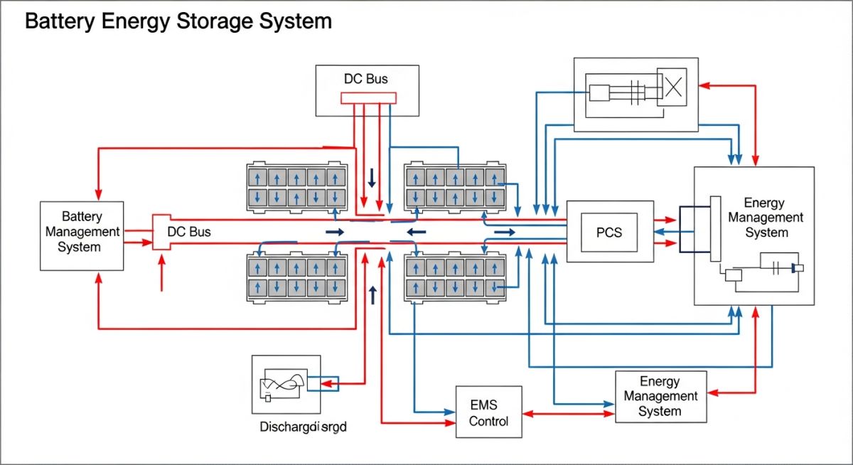
The Power Conversion System (PCS) acts as the bridge between the DC battery bus and the AC grid. It utilizes insulated-gate bipolar transistors (IGBTs) to perform pulse-width modulation (PWM), converting DC to AC during discharge and vice versa during charging. For grid-scale applications, we specify four-quadrant inverters that allow for independent control of active and reactive power, essential for meeting IEEE 1547 requirements for grid interconnection.
Engineering Limitation: Thermal Runaway
The energy density of modern lithium-ion cells creates a significant risk of thermal runaway if the cooling system fails. We must calculate the heat rejection rate (Q) using the formula Q = I squared * R_internal, where R_internal increases as the battery ages. If the HVAC or liquid cooling system cannot dissipate this heat, the internal temperature will exceed the electrolyte decomposition threshold, leading to fire.
The Energy Management System (EMS) sits at the top of the hierarchy. It receives external signals from the grid operator or local site controllers and translates them into setpoints for the PCS. The EMS must execute complex algorithms to optimize for peak shaving, frequency regulation, or arbitrage, all while respecting the physical constraints imposed by the BMS. Failure to properly tune the EMS control loops often leads to excessive cycling, which prematurely degrades the battery chemistry.
BESS Operational Trade-offs: A critical assessment of electrochemical storage performance versus capital expenditure and long-term maintenance requirements in industrial grid applications.
Engineering Advantages
- Sub-cycle Response: Inverters provide near-instantaneous frequency response, far exceeding traditional spinning reserves.
- Modular Scalability: Rack-based designs allow for incremental capacity expansion without redesigning the entire balance of plant.
- Four-Quadrant Support: Independent control of active and reactive power provides superior voltage regulation at the point of common coupling.
- High Round-Trip Efficiency: Modern lithium-ion systems achieve 85-92% efficiency, minimizing energy loss during conversion cycles.
Engineering Disadvantages
- Degradation Sensitivity: Cycle life is non-linearly dependent on depth-of-discharge (DoD) and ambient operating temperatures.
- Complex Fire Mitigation: Stringent UL 9540 compliance requires expensive fire suppression and gas venting infrastructure.
- PCS Harmonic Distortion: High-frequency switching can introduce total harmonic distortion (THD) into the grid, requiring robust filtering.
- High Maintenance Overhead: Cooling systems, sensors, and communication gateways require frequent calibration to ensure system-wide safety.
Industrial BESS Deployment: Strategic implementation of energy storage to solve specific grid-level power quality and economic optimization challenges.
Grid Frequency Regulation
BESS units provide primary frequency response by injecting or absorbing active power within milliseconds of a grid frequency deviation. This application requires high-power, low-energy density configurations designed for thousands of shallow cycles per year, ensuring the system remains within its optimal SoC window to respond to both over-frequency and under-frequency events.
Peak Shaving and Load Leveling
By discharging stored energy during peak demand periods, industrial facilities can significantly reduce their peak demand charges from utility providers. This requires the EMS to perform predictive load forecasting, ensuring the battery is fully charged during off-peak hours when electricity prices are at their lowest, thereby maximizing the economic return on the capital investment.
Renewable Energy Firming
Intermittent sources like wind and solar require BESS to smooth out power output fluctuations caused by cloud cover or wind gusts. The system acts as a buffer, absorbing excess generation and releasing it during lulls, which allows the facility to maintain a stable power profile that complies with strict grid interconnection agreements and power purchase contracts.
In my two decades of field experience, I have observed that the selection of battery chemistry and power conversion hardware is dictated by specific grid-scale performance metrics. Engineers must evaluate the round-trip efficiency, cycle life, and thermal management requirements before finalizing the site layout. The following table outlines the critical performance parameters that define the operational envelope for modern utility-scale storage installations.
These values represent industry-standard benchmarks for lithium-ion and flow battery technologies. When designing for frequency regulation or peak shaving, ensure your power conversion system (PCS) is sized to handle the peak discharge rates identified in the table below, while maintaining the necessary thermal headroom to prevent premature cell degradation.
The integration of Battery Energy Storage Systems into existing electrical infrastructure requires a precise mapping of hardware components to their respective control layers. My approach involves categorizing these entities by their primary function, whether it be power conversion, thermal regulation, or grid-level energy management. This matrix serves as a foundational reference for project engineers to ensure all subsystems communicate effectively.
By aligning these components with their relevant international standards, we mitigate the risk of interoperability failures during commissioning. Use this matrix to verify that your Battery Management System (BMS) and Energy Management System (EMS) are configured to handle the specific voltage and current profiles of your chosen battery chemistry, as defined by the governing electrical codes.
Site Verification for Battery Energy Storage Systems: Successful deployment hinges on rigorous pre-commissioning checks that validate both the physical integrity of the battery containers and the logical configuration of the control systems. In my experience, skipping these verification steps often leads to thermal runaway events or grid synchronization failures during the initial ramp-up phase.
- Thermal Management: Verify coolant flow rates and heat exchanger efficiency against NFPA 855 requirements.
- Grounding Integrity: Confirm all enclosure grounding paths meet IEEE 80 standards for fault current dissipation.
- Communication Latency: Test the EMS-to-PCS handshake protocol to ensure latency remains below 50ms for frequency response.
- Fire Suppression: Validate that the gas detection and suppression systems are integrated with the BMS emergency shutdown signal.
- Protection Coordination: Verify that DC-side circuit breakers are calibrated to the specific short-circuit current of the battery bank.
Always document the baseline state of the battery modules before the first charge cycle. This data is vital for future warranty claims and long-term performance degradation analysis. Ensure that all personnel on-site are trained in high-voltage safety protocols as outlined in NFPA 70E.
Problem: Thermal Instability in High-Density BESS
- Inadequate airflow distribution within the battery container led to localized hot spots.
- The BMS failed to trigger an emergency derating because the temperature sensors were improperly calibrated.
- Ambient humidity levels exceeded the manufacturer’s recommended operating range, causing condensation on busbars.
- Grid demand spikes forced the system to operate at 110% capacity for extended periods.
Outcome: Optimized Thermal Management and Grid Reliability
- Implemented a closed-loop liquid cooling system that reduced cell temperature variance by 40%.
- Recalibrated the BMS sensor array to provide real-time, high-fidelity thermal data to the EMS.
- Installed industrial-grade dehumidification units to maintain internal humidity below 60%.
- Achieved a 99.9% uptime for frequency regulation services over the subsequent 12-month operational period.
My recommendation for similar projects is to prioritize thermal redundancy. Never rely on a single cooling mechanism; always incorporate passive heat sinks alongside active cooling to ensure the system remains within safe operating limits during extreme grid events.
Frequently Asked Engineering Questions
How does the BMS prevent thermal runaway?
- Active cell balancing to prevent overcharging of individual cells.
- Real-time current limiting when temperature thresholds are approached.
- Hard-wired emergency disconnect signals that trigger when internal sensors detect rapid temperature spikes.
What is the role of the PCS in grid stability?
- Active and reactive power control to stabilize grid frequency and voltage.
- Seamless transition between grid-tied and islanded modes during outages.
- Harmonic filtering to ensure power quality meets IEEE 519 standards.
How do I calculate the required BESS capacity?
- The required discharge duration (e.g., 2-hour or 4-hour storage).
- The round-trip efficiency losses of the PCS and cabling.
- The state-of-health (SOH) degradation factor over the project’s design life.
Why is the EMS critical for revenue generation?
- Arbitrage operations by charging during low-price periods and discharging during peaks.
- Participation in ancillary service markets like frequency regulation.
- Long-term cycle optimization to minimize battery degradation costs.
What are the primary fire safety standards?
How does ambient temperature affect performance?
Complete Course on
Piping Engineering
Check Now
Key Features
- 125+ Hours Content
- 500+ Recorded Lectures
- 20+ Years Exp.
- Lifetime Access
Coverage
- Codes & Standards
- Layouts & Design
- Material Eng.
- Stress Analysis

📚 Recommended Resources: Battery Energy Storage Systems
Read these Guides
Related posts:
![Technical infographic showing the workflow of flood risk assessment for data centres, including hydrological inputs and mitigation strategies.]()
Flood Risk Assessment for Data Centres: Engineering Design Guide
![Isometric engineering rendering of a data centre campus featuring flood protection barriers and elevated utility infrastructure for disaster resilience.]()
Flood Protection Level Selection for Mission-Critical Data Centre Infrastructure
![Cross-section diagram of a data centre foundation showing soil strata, pile foundations, and groundwater monitoring wells for geotechnical analysis.]()
Geotechnical Requirements for Data Centres: A Structural Engineering Guide
![Civil 3D interface showing a 3D site grading model with color-coded cut and fill zones for earthwork optimization.]()
Optimizing Cut and Fill Operations Using Civil 3D and GIS
![3D digital terrain model showing site grading, flood protection levels, and cut-fill zones for industrial infrastructure development.]()
Establishing FPL and Estimating Cut Fill Quantities for Site Grading
![3D engineering model showing cut and fill optimization for industrial site grading and earthwork balancing.]()
Cut and Fill Optimization: 8 Engineering Studies for Site Grading