Wind Energy Explained: A Technical Guide for Modern Engineers
In my two decades of experience across industrial infrastructure, I have observed that few sectors demand as much interdisciplinary precision as wind energy. Moving beyond the basic concept of spinning blades, we must analyze the fluid dynamics of airfoils, the structural integrity of composite materials, and the complex grid synchronization required for utility-scale deployment.
This guide serves as a rigorous deep-dive into the physics and mechanical realities of wind power. Whether you are evaluating site-specific wind shear profiles or calculating the fatigue life of a turbine drivetrain, understanding these core principles is non-negotiable for any engineer operating in the renewable space.
Key Engineering Takeaways
- Mastering the Betz Limit for theoretical power extraction efficiency.
- Understanding the impact of Reynolds numbers on airfoil performance.
- Navigating IEC 61400 standards for turbine safety and structural design.
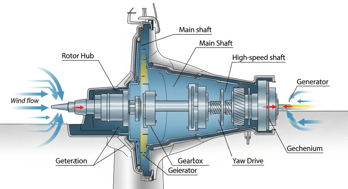
- Optimizing drivetrain mechanical efficiency through advanced lubrication and gear geometry.
Wind Energy Explained: Aerodynamics and Power Calculations
Wind Energy Explained: This section details the mathematical derivation of power extraction from wind streams, focusing on the relationship between air density, rotor swept area, and wind velocity as defined by the Betz Limit.
The fundamental power available in a wind stream is expressed by the kinetic energy equation. For an engineer, the power P is calculated as P equals one-half times air density rho times the swept area A times the cube of the wind velocity v. This cubic relationship is why even minor increases in wind speed result in exponential gains in potential energy output.
The Betz Limit and Efficiency
No turbine can capture 100 percent of the kinetic energy in the wind. If it did, the air would stop moving entirely behind the rotor, creating a blockage. The Betz Limit, established by Albert Betz in 1919, dictates that the maximum theoretical efficiency of a wind turbine is 16/27, or approximately 59.3 percent.
In practice, modern turbines achieve a power coefficient Cp ranging from 0.35 to 0.45. This loss is attributed to blade drag, tip losses, and mechanical friction within the gearbox and generator. When designing, we must account for the lift-to-drag ratio of the airfoil sections, typically using NACA profiles optimized for high Reynolds numbers.
Field Warning: Structural Fatigue and Turbulence
Turbulence intensity is the primary driver of structural fatigue in turbine blades. Engineers must reference IEC 61400-1 to ensure the design load cases (DLC) account for extreme wind gusts and wake effects from neighboring turbines. Failure to model these dynamic loads accurately leads to premature composite delamination and gearbox failure.
Aerodynamic Torque and Blade Pitch
To maintain optimal tip-speed ratios, modern turbines utilize active pitch control. By adjusting the angle of attack of the blades, the control system can maximize torque at low wind speeds and feather the blades during high-wind events to prevent structural overload. This is a critical control loop that requires high-speed sensor feedback and robust hydraulic or electric actuators.
The torque T generated is a function of the lift force acting on the blade chord. As the rotor speed increases, the relative wind velocity changes, requiring a dynamic adjustment of the pitch angle to maintain the optimal lift coefficient. This interaction is modeled using Blade Element Momentum (BEM) theory, which discretizes the blade into segments to calculate local forces.
Wind Energy Engineering Trade-offs: This analysis evaluates the operational benefits and structural challenges inherent in large-scale wind power deployment, focusing on lifecycle costs and grid stability.
Advantages
- Zero operational emissions during the power generation phase.
- Rapid scalability of modular turbine units for site-specific capacity.
- Low lifecycle carbon footprint compared to fossil fuel assets.
- Dual-use land potential, allowing agriculture beneath turbine arrays.
- Technological maturity with established supply chains for components.
Disadvantages
- Intermittent power output requiring energy storage or grid backup.
- High initial capital expenditure for offshore foundation installation.
- Complex logistics for transporting massive blade components.
- Acoustic and visual impact on local communities and wildlife.
- Requirement for specialized maintenance in harsh, remote environments.
Wind Energy Deployment Scenarios: This section outlines the diverse industrial and utility-scale applications where wind energy serves as a primary or supplemental power source.
Utility-Scale Grid Integration
Large-scale wind farms are integrated into national grids to provide bulk power. These installations utilize high-voltage direct current (HVDC) transmission to minimize losses over long distances, particularly for offshore arrays where the wind resource is more consistent and higher in velocity.
Green Hydrogen Production
Wind energy is increasingly coupled with PEM electrolyzers to produce green hydrogen. By utilizing excess wind power during off-peak hours, facilities can convert electrical energy into chemical energy, providing a carbon-neutral feedstock for industrial processes like ammonia synthesis and steel manufacturing.
Remote Microgrid Power
In isolated regions or mining operations, wind turbines are paired with battery energy storage systems (BESS) to create stable microgrids. This reduces reliance on expensive, carbon-intensive diesel generators and provides a reliable, localized power source that can operate independently of the main transmission network.
Desalination Plant Operations
Wind-powered reverse osmosis plants are becoming a viable solution for water security in coastal areas. By powering high-pressure pumps directly with wind energy, these facilities can produce potable water with minimal environmental impact, effectively decoupling water production from fossil fuel price volatility.
In my two decades of experience, selecting the correct turbine configuration requires a rigorous analysis of site-specific wind regimes and mechanical load profiles. The following table outlines the critical performance metrics that dictate the structural integrity and power output efficiency of modern utility-scale wind turbines, referencing IEC 61400 standards for design requirements.
Engineers must balance the cut-in speed, which defines the lower threshold for energy production, against the rated wind speed where the turbine reaches its nominal power capacity. Understanding these variables is essential for calculating the annual energy production (AEP) and ensuring that the drivetrain components, such as the gearbox and generator, are not subjected to premature fatigue failure due to excessive turbulence intensity or extreme wind gusts.
| Parameter | Typical Range | Engineering Impact |
|---|---|---|
| Cut-in Wind Speed | 3.0 – 4.5 m/s | Determines start-up reliability and low-wind site viability. |
| Rated Wind Speed | 12.0 – 15.0 m/s | Defines nominal power output and generator sizing. |
| Cut-out Wind Speed | 20.0 – 25.0 m/s | Safety threshold to prevent structural damage from storms. |
| Power Coefficient (Cp) | 0.35 – 0.50 | Efficiency of kinetic energy conversion to mechanical torque. |
These values serve as the baseline for site feasibility studies. Deviations from these ranges often necessitate custom blade pitch control algorithms or reinforced tower foundations to mitigate site-specific environmental stressors.
The complexity of wind energy systems requires a structured approach to mapping mechanical, electrical, and environmental entities. This matrix provides a high-level overview of the core components and their associated regulatory frameworks, which I have found to be the most critical for project lifecycle management and risk mitigation.
By aligning these entities with international standards, engineers can ensure interoperability between the turbine, the balance of plant (BoP), and the electrical grid. This mapping is particularly vital when dealing with offshore wind farms, where the harsh marine environment demands higher safety factors and specialized corrosion protection strategies as outlined in DNV-ST-0126.
| Entity | Primary Function | Standard Reference |
|---|---|---|
| Rotor Blades | Aerodynamic lift and torque generation | IEC 61400-5 |
| Tower Structure | Support and vibration damping | Eurocode 3 |
| Power Converter | Grid synchronization and frequency control | IEEE 1547 |
| Foundation | Load transfer to seabed or soil | DNV-ST-0126 |
Utilizing this matrix during the front-end engineering design (FEED) phase allows for a more cohesive integration of subsystems, reducing the likelihood of interface clashes during the construction and commissioning stages.
Site Verification Protocol: Ensuring the long-term viability of a wind energy project requires a systematic verification of environmental, logistical, and technical parameters. Before finalizing the turbine layout, I always mandate a comprehensive site audit to validate the assumptions made during the initial wind resource assessment.
-
Wind Resource Validation: Verify anemometer data against long-term historical meteorological records to ensure the P50 and P90 energy yield estimates are statistically sound. -
Geotechnical Survey: Conduct deep-soil analysis to confirm foundation design suitability, specifically checking for liquefaction risks or high water tables in coastal regions. -
Grid Connection Capacity: Confirm the local substation’s ability to handle the peak power injection without exceeding thermal limits or causing voltage instability. -
Logistical Access: Validate that road widths, bridge load ratings, and turning radii can accommodate the transport of oversized turbine blades and tower sections. -
Environmental Compliance: Ensure all noise, shadow flicker, and avian impact studies meet local regulatory requirements and environmental impact assessment (EIA) permits.
Each checkpoint must be signed off by the lead project engineer. Failure to address these items early in the project lifecycle often leads to significant cost overruns and schedule delays, particularly in remote or offshore locations where mobilization costs are prohibitive.
Problem: Premature Gearbox Failure in High-Turbulence Site
- Unexpected vibration signatures detected in the drivetrain after 18 months of operation.
- High turbulence intensity (TI) levels exceeding the original design class of the turbine.
- Inadequate lubrication cooling during peak summer wind events leading to thermal degradation.
- Misalignment between the main shaft and the gearbox input stage due to foundation settlement.
Outcome: Successful Mitigation and Reliability Restoration
- Implemented a predictive maintenance program using vibration analysis to monitor bearing health.
- Installed an upgraded active cooling system for the gearbox oil circuit.
- Adjusted the turbine control software to de-rate power output during high-turbulence wind sectors.
- Achieved a 15% reduction in unplanned downtime over the subsequent 24-month period.
My recommendation for similar projects is to prioritize high-fidelity wind resource modeling that accounts for local terrain-induced turbulence. Relying solely on regional wind maps is insufficient for complex terrain, where micro-scale wind phenomena can significantly impact the fatigue life of mechanical components.
Frequently Asked Engineering Questions
How does air density affect wind turbine power output?
Air density is a direct multiplier in the power equation, meaning that power output is linearly proportional to the density of the air passing through the rotor sweep. In my experience, engineers often overlook the impact of altitude and temperature on air density, which can lead to significant overestimation of energy yields.
- Cold, high-pressure air increases density, resulting in higher power output for the same wind speed.
- High-altitude sites experience lower air density, requiring larger rotor diameters to achieve the same nominal power.
- Seasonal temperature fluctuations must be integrated into the annual energy production (AEP) model to ensure accuracy.
What is the significance of the Betz Limit?
The Betz Limit defines the maximum theoretical efficiency of a wind turbine, stating that no turbine can capture more than 59.3 percent of the kinetic energy in the wind. This limit is derived from the conservation of mass and momentum in the stream tube passing through the rotor.
- It serves as the fundamental benchmark for aerodynamic design and blade optimization.
- Modern turbines typically achieve 75 to 80 percent of the Betz Limit, which is considered highly efficient.
- Exceeding this limit is physically impossible, as it would require the wind to stop completely behind the rotor, which would prevent further air flow.
Why is turbulence intensity a critical design factor?
Turbulence intensity (TI) represents the standard deviation of wind speed fluctuations relative to the mean wind speed. High TI levels introduce cyclic loading on the turbine blades and drivetrain, significantly accelerating fatigue damage.
- Turbines are classified by IEC standards based on their ability to withstand specific turbulence levels.
- High-TI sites require more robust structural components and advanced pitch control systems to dampen loads.
- Neglecting TI during the design phase is a leading cause of premature component failure in complex terrain.
How do offshore foundations differ from onshore?
Offshore foundations must account for hydrodynamic loads, including wave action, current forces, and potential scour around the base. Unlike onshore foundations, which primarily deal with gravity and wind-induced overturning moments, offshore structures require specialized corrosion protection and marine-grade materials.
- Monopiles, jackets, and floating platforms are common offshore solutions depending on water depth.
- Installation requires heavy-lift vessels and precise subsea engineering to ensure structural stability.
- Maintenance access is significantly more complex and costly, necessitating higher reliability standards for all subsea components.
What role does the power converter play in grid integration?
The power converter is the interface between the variable-frequency generator output and the fixed-frequency grid. It allows the turbine to operate at variable speeds, which maximizes aerodynamic efficiency across a wide range of wind speeds.
- It provides reactive power control, which is essential for maintaining grid voltage stability.
- Modern converters include fault-ride-through capabilities to keep the turbine connected during grid disturbances.
- Harmonic filtering is integrated to ensure the power quality meets strict utility interconnection standards.
How is the annual energy production (AEP) calculated?
AEP calculation involves integrating the turbine power curve with the site-specific wind speed probability distribution, typically represented by a Weibull distribution. This calculation must account for various losses to provide a realistic estimate of net energy production.
- Wake losses from neighboring turbines in a wind farm must be subtracted from the gross output.
- Availability factors account for scheduled maintenance and unplanned downtime.
- Electrical losses in the collection system and transformers are factored in to determine the final energy delivered to the grid.
Complete Course on
Piping Engineering
Check Now
Key Features
- 125+ Hours Content
- 500+ Recorded Lectures
- 20+ Years Exp.
- Lifetime Access
Coverage
- Codes & Standards
- Layouts & Design
- Material Eng.
- Stress Analysis

📚 Recommended Resources: Wind Energy Explained
Read these Guides
- 📄 Solar Energy Explained: A Comprehensive Technical Guide for Engineers
- 📄 Solar Tracking Systems Explained: Optimizing Energy Yield and Efficiency
- 📄 Solar Inverters Explained: Design, Selection, and Operational Efficiency Guide
- 📄 Solar Panels Explained: Types, Working Principles, and Selection Criteria