How to Use a Pump Installation Checklist for Maximum Reliability
In my 20 years of piping engineering, I have seen millions of dollars wasted on premature pump failures. The root cause is rarely a manufacturing defect. Instead, it is almost always a failure in the field during the installation phase. A pump is not a standalone machine; it is the heart of a complex piping system. If you do not isolate it from external forces, thermal expansion, and foundation vibrations, it will fail.
I remember a project in Gujarat where a massive double-suction cooling water pump suffered catastrophic bearing failure within 72 hours of startup. The field team blamed the pump manufacturer. However, when my team performed a laser alignment check and unbolted the suction flange, the pipe sprang back by nearly 12 millimeters. The pump casing was warped by massive pipe strain. This expensive disaster could have been avoided by using a rigorous, step-by-step field verification process.
Key Engineering Takeaways
- Eliminate pipe strain by verifying flange alignment before tightening bolts.
- Ensure foundation mass is at least three to five times the total mass of the pump and driver assembly.
- Perform final shaft alignment only after the piping is fully supported and hydrotested.
- Verify that the Net Positive Suction Head available exceeds the required margin by at least 1.5 meters.
Why Every Project Needs a Pump Installation Checklist
Installation Quality Control: The systematic execution of pre-commissioning checks to eliminate pipe strain, soft foot, and misalignment. This process guarantees that the physical installation matches the design parameters specified in API RP 686.
When we talk about rotating equipment, precision is everything. A standard centrifugal pump operating at 3600 RPM rotates 60 times every single second. At these speeds, even microscopic misalignments generate massive dynamic forces that destroy mechanical seals and bearings. To prevent this, we must focus on three core areas: foundation design, piping strain elimination, and shaft alignment.
1. Foundation and Grouting Design
The foundation must act as a rigid anchor that absorbs vibration. As a rule of thumb, for concrete foundations, the mass of the foundation block must be at least three times the mass of the pump and motor for centrifugal pumps, and five times the mass for reciprocating pumps.
Grouting is the structural link between the pump baseplate and the concrete foundation. Epoxy grout is preferred over cementitious grout for heavy industrial applications because of its superior chemical resistance, high tensile strength, and low shrinkage properties.
Never pour epoxy grout when the ambient temperature is below 15 degrees Celsius or above 35 degrees Celsius. Low temperatures prevent complete polymerization, leaving the grout weak and prone to cracking under dynamic loads. High temperatures cause rapid curing, leading to thermal cracking and voids beneath the baseplate.
2. Eliminating Pipe Strain
Piping strain occurs when the suction and discharge pipes do not align perfectly with the pump nozzles, forcing the field team to use external force (such as come-alongs or chain hoists) to align the bolt holes. This introduces massive static loads directly into the pump casing.
To calculate the maximum allowable force on pump nozzles, we refer to API 610 Table 5. The golden rule of piping design is that the pump must not be used as a pipe support. The piping must be fully supported by independent hangers and guides.
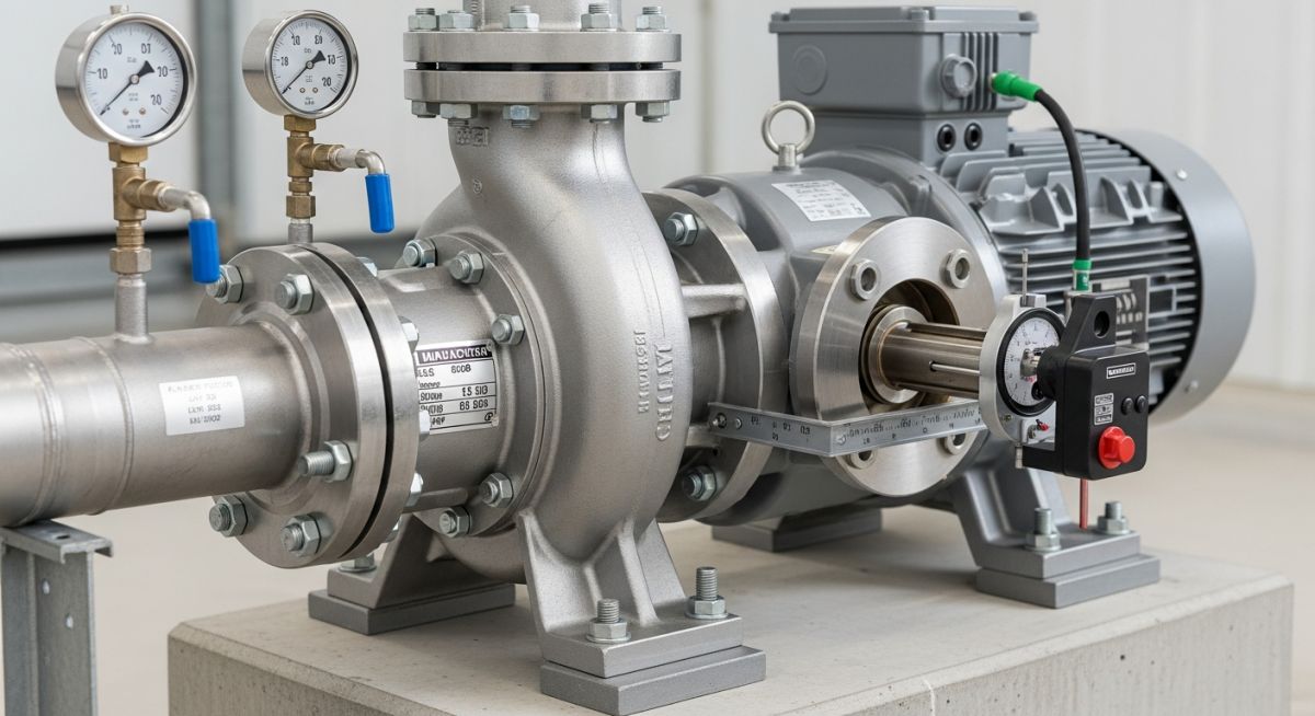
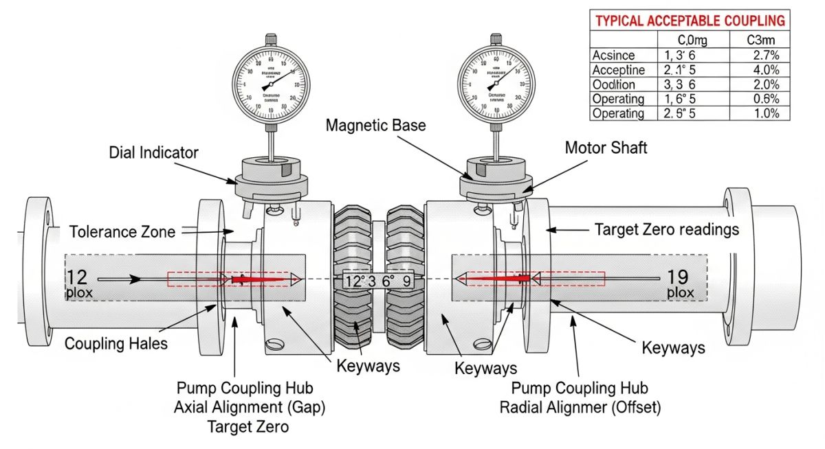
To verify zero pipe strain during installation, mount dial indicators on the pump coupling. Monitor the dial indicators while tightening the suction and discharge flange bolts. If the shaft moves more than 0.05 millimeters (0.002 inches) in any direction, the piping alignment is unacceptable and must be corrected.
3. Net Positive Suction Head (NPSH) Verification
Cavitation is the formation and subsequent collapse of vapor bubbles inside the pump impeller due to low pressure. To prevent cavitation, the Net Positive Suction Head Available (NPSHa) must be greater than the Net Positive Suction Head Required (NPSHr) by the pump.
The engineering formula for NPSHa is:
Where:
– Ha is the absolute pressure on the surface of the liquid in the suction vessel.
– Hs is the static height of the liquid above the pump centerline (positive for flooded suction, negative for suction lift).
– Hf is the friction loss in the suction piping system.
– Hvp is the vapor pressure of the liquid at the pumping temperature.
The following table outlines the maximum allowable alignment tolerances for industrial pumps based on operating speed, in accordance with API RP 686 guidelines.
| Operating Speed (RPM) | Max Radial Offset (mm) | Max Angular Pitch (mm/mm) | Grout Type Recommendation |
|---|---|---|---|
| Up to 1500 | 0.08 | 0.0008 | Cementitious or Epoxy |
| 1501 to 3000 | 0.05 | 0.0005 | Epoxy Grout Only |
| 3001 to 3600 | 0.03 | 0.0003 | High-Performance Epoxy |
| Above 3600 | 0.02 | 0.0002 | Specialist Polymer Grout |
This matrix maps critical installation parameters to their corresponding engineering standards, physical units, and field verification methods.
| Technical Parameter | Standard Reference | Target Value / Limit | Verification Tool |
|---|---|---|---|
| Soft Foot Tolerance | API RP 686 | Less than 0.05 mm | Dial Indicator / Feeler Gauge |
| Suction Pipe Straight Run | ASME B73.1 | Minimum 5 to 10 times Pipe Diameter | Physical Tape Measure |
| Baseplate Flatness | API 610 | 0.42 mm per meter | Precision Spirit Level |
| Flange Parallelism | ASME B31.3 | Gap variation less than 0.4 mm | Calibrated Vernier Calipers |
Pre-Commissioning Verification: A field-level inspection sequence executed by mechanical technicians to validate the physical state of the pump assembly before startup. This checklist enforces compliance with ASME B31.3 piping design rules and manufacturer installation manuals.
I have developed this checklist over two decades of managing refinery and chemical plant installations. Every item on this list represents a lesson learned from a real-world failure. Do not skip any of these steps.
Field Verification Checklist
Verify concrete foundation is fully cured (minimum 28 days for standard concrete). Ensure the surface is chipped to expose sound aggregate before placing the baseplate.
Level the baseplate using stainless steel shims or leveling screws. Verify leveling with a master precision level (accuracy of 0.05 mm per meter). Pour epoxy grout, ensuring no air pockets or voids remain.
Loosen one hold-down bolt at a time while monitoring a dial indicator on the foot. If movement exceeds 0.05 mm, add shims under that foot to eliminate the gap.
Align piping flanges to pump nozzles. Verify that flange faces are parallel within 0.4 mm and bolt holes align without force. Monitor coupling indicators during final bolt-up to ensure zero shaft movement.
Perform final laser alignment of the pump and motor shafts. Account for thermal growth if the pump operates at high temperatures (above 100 degrees Celsius).
Verify correct motor rotation direction with the coupling spacer removed. Hand-rotate the shaft to ensure free movement without binding. Fill the bearing housing with the correct grade of oil.
Field Case Study: Real-World Application
At a combined-cycle power plant, a newly installed 450 kW boiler feed pump experienced severe vibration levels of 12.4 mm/s RMS during its initial run. This far exceeded the allowable limit of 3.0 mm/s RMS specified by ISO 10816-3. The operations team suspected a bent shaft or an unbalanced impeller and demanded a complete pump teardown, which would have delayed the plant startup by two weeks.
I was called to the site to investigate. Instead of pulling the pump apart, I insisted on executing our standard pump installation checklist. We first uncoupled the motor and checked for soft foot; we found a 0.18 mm gap under the outboard motor foot. Next, we unbolted the suction flange and observed a massive lateral pipe spring of 8.5 mm.
We corrected the soft foot with precision stainless steel shims. We then cut and re-welded the suction piping spool to achieve perfect flange alignment without strain. After re-aligning the shaft to within 0.02 mm of radial offset, we restarted the pump. Vibration levels dropped to an exceptionally quiet 1.4 mm/s RMS. The project was saved from a costly delay, saving the client over 120,000 in unnecessary maintenance and downtime.
My recommendation is simple: never assume that piping or foundations are correct just because they look right. Always measure, always document, and always enforce the checklist before you press the start button.
Frequently Asked Engineering Questions
What is the maximum allowable pipe strain on a pump flange?
Why is epoxy grout preferred over cementitious grout for heavy industrial pumps?
How does soft foot affect pump shaft alignment?
What is the minimum straight run of pipe required at the pump suction nozzle?
How do you perform a field check for NPSH margin adequacy?
What are the primary causes of premature mechanical seal failure during initial startup?
Complete Course on
Piping Engineering
Check Now
Key Features
- 125+ Hours Content
- 500+ Recorded Lectures
- 20+ Years Exp.
- Lifetime Access
Coverage
- Codes & Standards
- Layouts & Design
- Material Eng.
- Stress Analysis