Why Stress Intensification Factor in Piping Dictates Fatigue Life
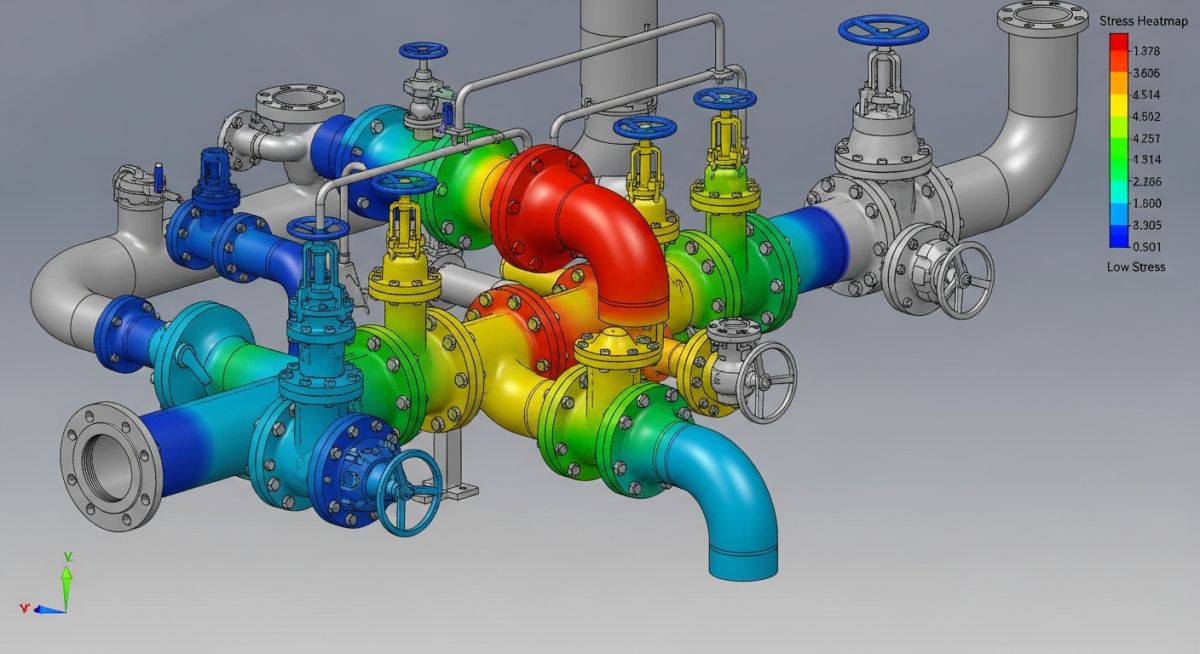
In my 20-plus years of troubleshooting piping failures across petrochemical plants and power stations, I have seen spectacular, costly disasters that all trace back to a single overlooked variable. I am talking about the Stress Intensification Factor in Piping. Many young engineers treat this factor as a black-box number that stress analysis software like Caesar II automatically spits out. This is a dangerous mistake. When a high-pressure steam line or a hazardous chemical header undergoes thermal expansion, the stress does not distribute evenly. It concentrates at the fittings—the elbows, tees, and branch connections. If you do not understand how these factors are derived and applied, you are essentially designing a ticking time bomb.
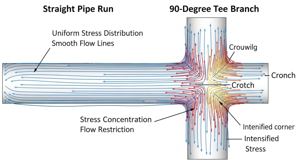
The concept of the Stress Intensification Factor (SIF) was born out of necessity. In the mid-20th century, pioneering researchers like A.R.C. Markl conducted extensive fatigue tests on full-scale piping components. They discovered that geometric discontinuities, such as the crotch of a tee or the sharp toe of a fillet weld, act as severe stress risers. Under cyclic thermal expansion, these locations are the first to develop micro-cracks, leading to catastrophic fatigue failure. By understanding and managing these factors, we can design piping systems that safely absorb thermal expansion cycles over a 30-year operating life without cracking.
Key Engineering Takeaways
- Fatigue-Driven Multiplier: SIF is a fatigue-based multiplier, not a static stress concentration factor, developed specifically for cyclic thermal analysis.
- Code Compliance: Modern designs rely on ASME B31.3 Appendix D and the newer ASME B31J standards for accurate calculations.
- Weld Quality Matters: The physical profile of a weld in the field directly influences the actual SIF, making field inspection a critical safety step.
Calculating the Stress Intensification Factor in Piping Systems
To truly master piping stress analysis, we must look at the math behind the magic. The Stress Intensification Factor, denoted as “i”, is fundamentally tied to the geometry of the component. Let us examine a standard welding elbow. The geometry of an elbow causes it to flatten when subjected to a bending moment. This flattening behavior increases the flexibility of the elbow but also concentrates the stresses at the crown.
The governing parameter for this behavior is the flexibility characteristic, represented by the letter “h”. For a standard welding elbow, the formula for “h” is:
Where:
– t is the nominal wall thickness of the matching pipe.
– R is the bend radius of the elbow.
– r is the mean radius of the matching pipe (outer diameter minus wall thickness, divided by two).
Once we have calculated the flexibility characteristic “h”, we can determine the in-plane and out-of-plane SIFs using the standard ASME B31.3 formulas:
Out-of-Plane SIF (i_out) = 0.75 / (h^(2/3))
Notice that the in-plane SIF is higher than the out-of-plane SIF. This is because in-plane bending directly forces the elbow to flatten, whereas out-of-plane bending introduces a combination of torsion and bending that distributes the stress slightly differently. If you are analyzing a system with high thermal cycles, these values will scale your nominal bending stresses significantly, sometimes by a factor of three or four.
In my consulting practice, I often review stress models where the analyst left the SIF input blank, assuming the software would automatically apply the correct value. If the software does not know the exact weld profile (such as whether a branch is a stub-in or a forged Weldolet), it may default to a conservative or, worse, an unconservative value. Always manually verify the component type and weld details in your stress model.
In recent years, the piping industry has transitioned from the traditional Appendix D formulas to the more comprehensive ASME B31J standard. ASME B31J provides updated, experimentally validated SIFs and flexibility factors. It resolves many of the conservative biases found in the older codes, particularly for branch connections and tees. Using B31J can often reduce calculated stresses in your system, saving you from adding unnecessary expansion loops or spring hangers.
The table below outlines the standard flexibility characteristics and SIF formulas for common piping components as per ASME B31.3. These values are critical for manual verification of your stress analysis software outputs.
| Piping Component | Flexibility Characteristic (h) | In-Plane SIF (i_in) | Out-of-Plane SIF (i_out) | Typical SIF Range |
|---|---|---|---|---|
| Welding Elbow (LR) | t * R / r^2 | 0.9 / h^(2/3) | 0.75 / h^(2/3) | 1.2 – 2.5 |
| Welding Tee (ASME B16.9) | 4.4 * t / r | 0.9 / h^(2/3) | 0.75 / h^(2/3) | 1.5 – 3.0 |
| Reinforced Fabricated Tee | (t + 0.5 * T)^2.5 / (t^1.5 * r) | 0.9 / h^(2/3) | 0.75 / h^(2/3) | 2.0 – 4.0 |
| Unreinforced Fabricated Tee | t / r | 0.9 / h^(2/3) | 0.75 / h^(2/3) | 3.0 – 6.0 |
This matrix maps the core technical entities, structural acronyms, and physical parameters associated with piping stress analysis and SIF validation.
| Entity / Acronym | Physical Parameter | Governing Code | Primary Impact on Design |
|---|---|---|---|
| SIF (i) | Stress Intensification Factor | ASME B31.3 | Multiplies nominal bending stress to calculate fatigue life. |
| FEA | Finite Element Analysis | ASME B31J | Provides highly accurate, component-specific SIF values. |
| Flexibility Factor (k) | Rotational flexibility multiplier | ASME B31.1 | Reduces system stiffness, lowering overall thermal expansion forces. |
| WOL | Weldolet (Forged Branch) | MSS SP-97 | Provides integral reinforcement, significantly lowering the branch SIF. |
Verifying Stress Intensification Factor in Piping Designs
As a lead engineer, I have learned that what is modeled on a computer screen does not always match what is built in the field. A stress analyst might assume a smooth, forged tee, while the field crew installs a cheap, unreinforced fabricated stub-in. This discrepancy can lead to premature fatigue failure. Therefore, a rigorous verification process is necessary before releasing any piping system for fabrication.
Field & Design Verification Checklist
-
Verify Branch Connection Types: Ensure that all branch connections (Weldolets, Threadolets, Sweepolets, or fabricated tees) match the exact SIF inputs used in the stress model. -
Inspect Weld Profiles: Confirm that fillet welds on branch connections have a smooth, concave transition to minimize the local stress concentration. -
Check Wall Thickness Schedules: Validate that the matching pipe schedules on both the run and branch lines match the design drawings, as thickness directly impacts the flexibility characteristic “h”. -
Review Reinforcement Pad Dimensions: If a reinforcement pad (repad) is used, verify that its width, thickness, and weld size match the stress isometric. -
Confirm ASME B31J Application: Ensure that the stress analysis software has the ASME B31J option enabled for more realistic and less overly conservative SIF calculations.
Field Case Study: Real-World Application
The Problem: Recurring Fatigue Cracking in a Steam Bypass Line
At a combined-cycle power plant, a 12-inch high-pressure steam line operating at 380°C experienced recurring cracking at a 4-inch bypass branch connection. The line underwent daily thermal cycling due to peaking operations. The original design team had modeled the branch as a standard welding tee. However, during my site audit, I discovered that the field team had actually installed an unreinforced fabricated stub-in. Because the stub-in had a significantly higher SIF (approximately 4.1) compared to the modeled welding tee (approximately 1.8), the actual localized stress was more than double what the software had predicted, leading to fatigue cracking in less than 18 months of operation.
The Outcome: Redesign and SIF Optimization
I immediately revised the stress model to reflect the as-built stub-in, which confirmed that the thermal expansion stresses exceeded the ASME B31.3 allowable limits. To resolve the issue permanently, we replaced the fabricated stub-in with a forged integrally reinforced outlet fitting (Weldolet) and updated the stress model using the precise SIF calculations from ASME B31J. This modification reduced the SIF from 4.1 to 1.6. The calculated stress dropped well within the safe allowable limits, and the line has now operated for over six years without a single sign of cracking.
This case study highlights why we cannot afford to treat SIF as an afterthought. A simple geometric change in the field completely altered the fatigue life of the system. Always ensure that your design specifications are strictly followed during construction, and perform field audits on critical, high-temperature systems.
Frequently Asked Engineering Questions
What is the difference between a stress concentration factor (Kt) and a stress intensification factor (i)?
How does ASME B31J improve upon the traditional ASME B31.3 Appendix D SIF values?
Why do in-plane and out-of-plane SIFs differ for the same piping component?
Can a weld overlay or grinding the weld toe reduce the SIF of a joint?
How do thermal expansion cycles affect the fatigue life of high-SIF fittings?
What is the role of the flexibility characteristic (h) in determining SIF?
===FAQ_BLOCK===
Complete Course on
Piping Engineering
Check Now
Key Features
- 125+ Hours Content
- 500+ Recorded Lectures
- 20+ Years Exp.
- Lifetime Access
Coverage
- Codes & Standards
- Layouts & Design
- Material Eng.
- Stress Analysis


