What Does a Pipe Stress Engineer Need to Know?
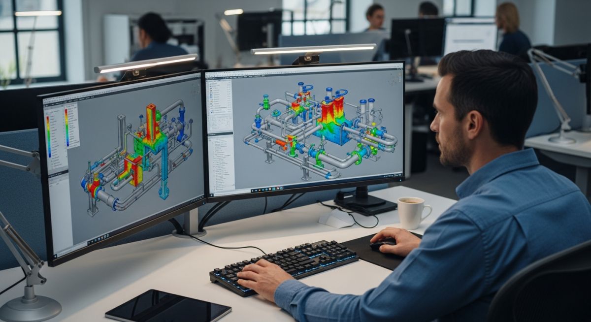
In my 20+ years of piping engineering experience, I have seen countless designs look perfect on a 3D CAD screen, only to tear themselves apart at the first thermal cycle in the field. As a Pipe Stress Engineer, your job is to bridge the gap between theoretical design and physical reality. You are the last line of defense against catastrophic piping failures, flange leaks, and equipment nozzle damage.
To succeed in this demanding role, you must master a blend of structural mechanics, material science, code compliance, and software simulation. It is not just about pushing buttons in CAESAR II; it is about understanding the underlying physics of how piping materials behave under extreme pressures and temperatures.
Key Takeaways for Aspiring Stress Engineers:
- Differentiate clearly between sustained, displacement, and occasional loads.
- Master the application of ASME B31.3 Process Piping and ASME B31.1 Power Piping codes.
- Understand how to model realistic boundary conditions, including support friction and equipment nozzle flexibilities.
- Learn to design effective expansion loops and select the correct spring hangers.
What Must a Pipe Stress Engineer Master?
A competent Pipe Stress Engineer must categorize and analyze three primary types of loads: sustained, displacement, and occasional. Each load type has a distinct physical behavior and is governed by specific code limits.
1. Sustained Loads (Weight and Pressure)
Sustained loads are non-self-limiting. This means that if the stress exceeds the yield strength of the material, the piping will continue to deform until it collapses. The primary sources are the weight of the pipe, fittings, insulation, fluid, and internal design pressure.
The longitudinal stress due to sustained loads, SL, is calculated using the following code equation:
Where:
• P = Internal design pressure
• D = Outside diameter of the pipe
• t = Nominal wall thickness minus corrosion allowance
• i = Stress Intensification Factor (SIF)
• MA = Sustained bending moment due to weight
• Z = Section modulus of the pipe
• Sh = Basic allowable stress of the material at the design temperature
2. Displacement Loads (Thermal Expansion)
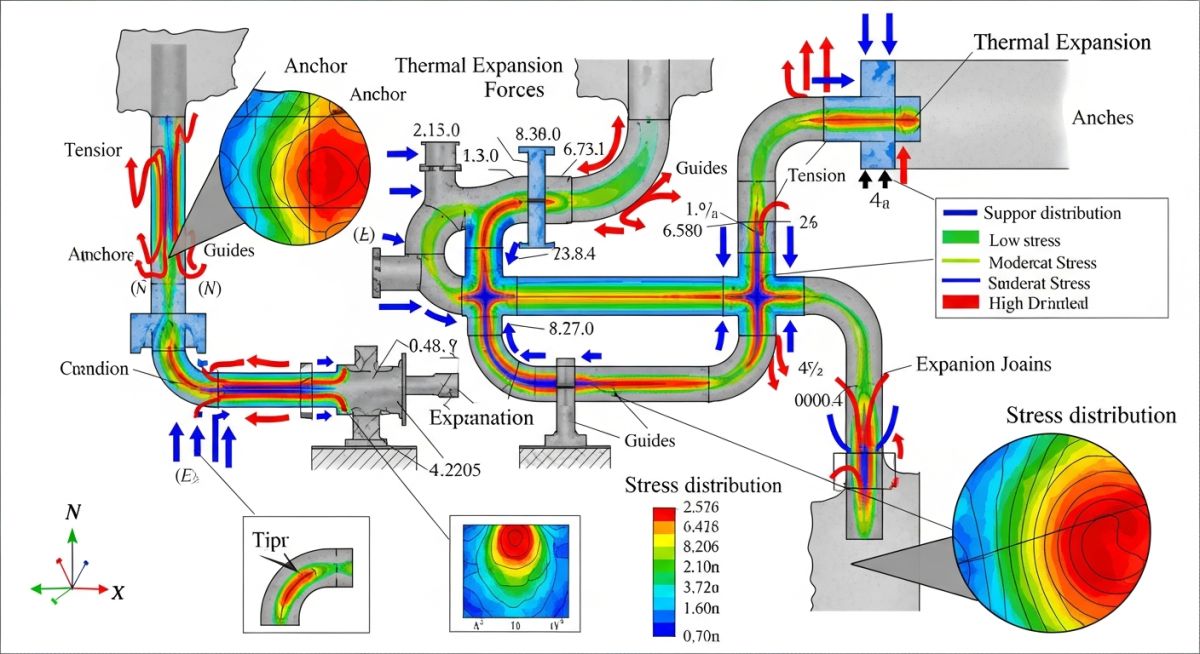
Unlike sustained loads, thermal expansion loads are self-limiting. When a pipe heats up, it expands. If this expansion is restricted by anchors or guides, thermal stresses develop. Once the pipe yields locally, the strain is accommodated, and the stress relaxes.
The expansion stress range, SE, is calculated as:
Where Sb is the resultant bending stress, St is the torsional stress, and SA is the allowable displacement stress range, defined by:
Where Sc is the basic allowable stress at the minimum metal temperature (usually ambient), and f is the stress range reduction factor, which accounts for the total number of thermal cycles over the lifetime of the plant.
In my experience, assuming frictionless supports in CAESAR II is a recipe for structural failure. Always input realistic friction coefficients (typically 0.3 for steel-on-steel, 0.1 for Teflon-on-steel) to prevent unexpected nozzle loads on sensitive equipment like pumps and turbines.
3. Occasional Loads (Wind, Seismic, and Water Hammer)
These are short-duration loads. Wind and seismic loads are calculated based on local building codes (such as ASCE 7). Water hammer is a dynamic fluid transient that requires time-history analysis to determine the transient forces acting on piping elbows.
How Does a Pipe Stress Engineer Calculate Expansion?
To design an effective piping system, you must know how different materials expand and their corresponding allowable stresses. The table below provides critical design data for common piping materials at an operating temperature of 200 degrees Celsius.
| Material Specification | Nominal Composition | Mean Thermal Expansion (mm/m at 200°C) | Allowable Stress Sh at 200°C (MPa) | Common Application |
|---|---|---|---|---|
| ASTM A106 Gr. B | Carbon Steel | 2.18 | 138 | Steam, Condensate, Hydrocarbons |
| ASTM A312 TP304 | 18Cr-8Ni Stainless Steel | 3.24 | 115 | Corrosive Fluids, High Purity |
| ASTM A335 Gr. P11 | 1.25Cr-0.5Mo Alloy Steel | 2.10 | 138 | High-Temperature Steam Lines |
| ASTM B165 | Nickel-Copper (Monel 400) | 2.85 | 112 | Marine, Acidic Environments |
Technical Mapping & Specifications Matrix
The following matrix maps core technical entities, their structural acronyms, physical parameters, and primary standard references that every stress engineer must reference daily.
| Technical Entity | Core Acronym | Physical Parameter | Primary Standard Reference |
|---|---|---|---|
| Stress Intensification Factor | SIF | Fatigue strength reduction factor at fittings | ASME B31J |
| Spring Hanger Preset | SHP | Pre-compressed load setting for variable springs | MSS SP-58 |
| Allowable Stress Range | ASR | Maximum permissible thermal expansion stress limit | ASME B31.3 Section 302.3.5 |
| Water Hammer Transient | WHT | Dynamic pressure surge force over time | ASME B31.1 Appendix II |
Piping Stress Site Verification Checklist
Before any process plant goes live, the physical installation must be verified against the approved stress analysis design. Discrepancies between the CAESAR II model and the actual field installation are a primary cause of premature piping failures.
Field Verification Checkpoints:
-
Cold Spring Settings: Verify that any designed cold spring or cold pull matches the stress isometric drawings exactly and has been executed using calibrated tensioning equipment. -
Spring Hanger Shipping Pins: Confirm that all temporary travel stops and shipping bars on variable or constant spring hangers are physically removed before hydrotesting. -
Guide Clearances: Inspect all pipe guides to ensure they have the specified radial clearance (typically 1.5 mm to 3 mm) to allow axial movement while restricting lateral displacement. -
Expansion Joint Alignment: Ensure that bellows-type expansion joints are installed without any unintended angular or lateral offset, and that shipping rods are removed. -
Equipment Nozzle Alignment: Verify that the final piping connection to sensitive equipment (pumps, compressors, turbines) is aligned within the strict tolerances specified by API RP 686.
Field Case Study: Real-World Application
A high-pressure steam line (400°C, 40 bar) connected to a steam turbine nozzle was experiencing severe vibration and causing the turbine casing to distort. The original design had assumed rigid anchors at the turbine nozzle and did not account for the actual thermal growth of the header. This resulted in nozzle loads that exceeded the limits specified in API Standard 611 by over 300%, risking catastrophic casing failure.
I led the redesign team to model the system in CAESAR II. We replaced two rigid guides with variable spring hangers and added a 3D expansion loop near the header. This modification reduced the thermal nozzle loads to 45% of the API 611 allowable limits. During commissioning, the turbine operated with minimal vibration, and casing alignment remained well within tolerance, saving the plant from an estimated 1.2 million in potential downtime.
My direct recommendation for any Pipe Stress Engineer facing high nozzle loads is to avoid adding rigid supports near equipment. Instead, look for opportunities to introduce flexibility through piping routing changes, expansion loops, or spring supports.
Frequently Asked Engineering Questions
What is the difference between sustained and expansion stresses?
How do you calculate the Stress Intensification Factor (SIF)?
Why is the cold spring method used in piping design?
How does a Pipe Stress Engineer handle nozzle loads on pumps?
What is the significance of the stress range reduction factor (f)?
When should variable spring hangers be used instead of constant support hangers?
===FAQ_BLOCK===
Complete Course on
Piping Engineering
Check Now
Key Features
- 125+ Hours Content
- 500+ Recorded Lectures
- 20+ Years Exp.
- Lifetime Access
Coverage
- Codes & Standards
- Layouts & Design
- Material Eng.
- Stress Analysis