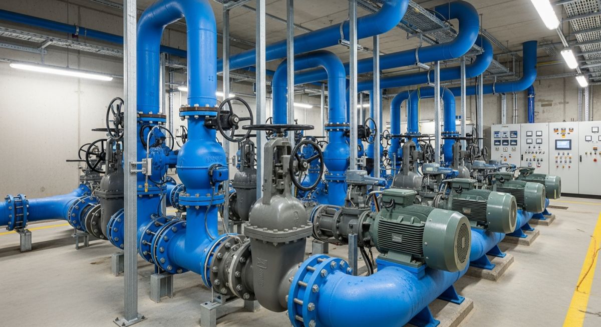
When is Pipe Stress Analysis for Cold Water Piping Required?
In my 20+ years of piping engineering experience, I have lost count of how many times a project manager has told me, “Atul, it is just cold water. Why are we spending money on a stress analysis?” It is a common misconception that because cold water piping operates near ambient temperatures, it is immune to structural failures. This assumption is not only incorrect, but it can also lead to catastrophic pump nozzle failures, flange leaks, and structural support collapses at pump stations.
While hot process lines demand attention due to obvious thermal expansion, cold water systems in municipal and industrial pump stations present unique structural challenges. These systems often feature large-diameter, heavy, water-filled lines subjected to massive hydraulic transients, equipment vibrations, and strict nozzle load limitations. Ignoring these factors during the design phase is a recipe for operational disaster.
- Ambient temperature does not eliminate the risk of thermal stress caused by solar radiation or seasonal environmental shifts.
- Large-bore water piping exerts massive static deadweight loads that can easily deform pump casings if not properly supported.
- Hydraulic transients, commonly known as water hammer, generate dynamic forces that require rigorous structural evaluation.
- Compliance with ASME B31.3 Process Piping or ASME B31.9 is often legally mandated, regardless of fluid temperature.
- Flexible connections and expansion joints must be modeled accurately to prevent transferring thrust forces to sensitive pump nozzles.
Determining the Need for Pipe Stress Analysis for Cold Water Piping
Cold Water Piping Stress Evaluation: The engineering assessment of static and dynamic loads on ambient-temperature water lines to prevent catastrophic pump nozzle failure and piping fatigue under transient operating conditions in accordance with ASME B31.3 guidelines.
To determine whether a formal computer-aided pipe stress analysis is required for your cold water system, we must look beyond temperature. The primary drivers for stress analysis in pump stations are pipe diameter, wall thickness, pump nozzle sensitivity, and hydraulic transient potential. When large-bore piping (typically NPS 10 and larger) connects to rotating equipment like centrifugal pumps, the allowable forces and moments on the pump nozzles are incredibly restrictive.
For instance, pump manufacturers design equipment to meet API 610 or ISO 5199 nozzle load limits. These standards allow very little external force. A 24-inch water-filled pipe can easily exceed these limits through deadweight alone if the support span is slightly off.
The Physics of Cold Water Piping Loads
Let us look at the math. The weight of a 24-inch Schedule 40 carbon steel pipe filled with water is approximately 430 kg/m (289 lb/ft). If you have a 10-meter unsupported run leading directly to a pump suction nozzle, that nozzle is subjected to a static force of 4,300 kg (nearly 9,500 lbs). This does not account for the dynamic forces of water flowing at 3 meters per second, or the sudden pressure spike from a valve closure.
Even thermal expansion cannot be completely ignored. Consider an outdoor municipal pump station where the piping is installed during a winter shutdown at 5°C (41°F). In the peak of summer, with the pump idle and exposed to direct solar radiation, the metal temperature can easily reach 50°C (122°F).
The linear thermal expansion is calculated using the standard formula:
Where:
• dL = Linear expansion (meters)
• alpha = Coefficient of thermal expansion for carbon steel (approximately 11.7 x 10^-6 m/m/°C)
• L = Length of the pipe run (50 meters)
• dT = Temperature differential (50°C – 5°C = 45°C)
Calculating this yields:
Over 26 mm of thermal expansion in a rigid, unanalyzed piping system will easily crush a pump nozzle, crack a valve body, or tear out anchor bolts. This is why a formal stress analysis is critical, even for “cold” water.
ASME Code Compliance Requirements
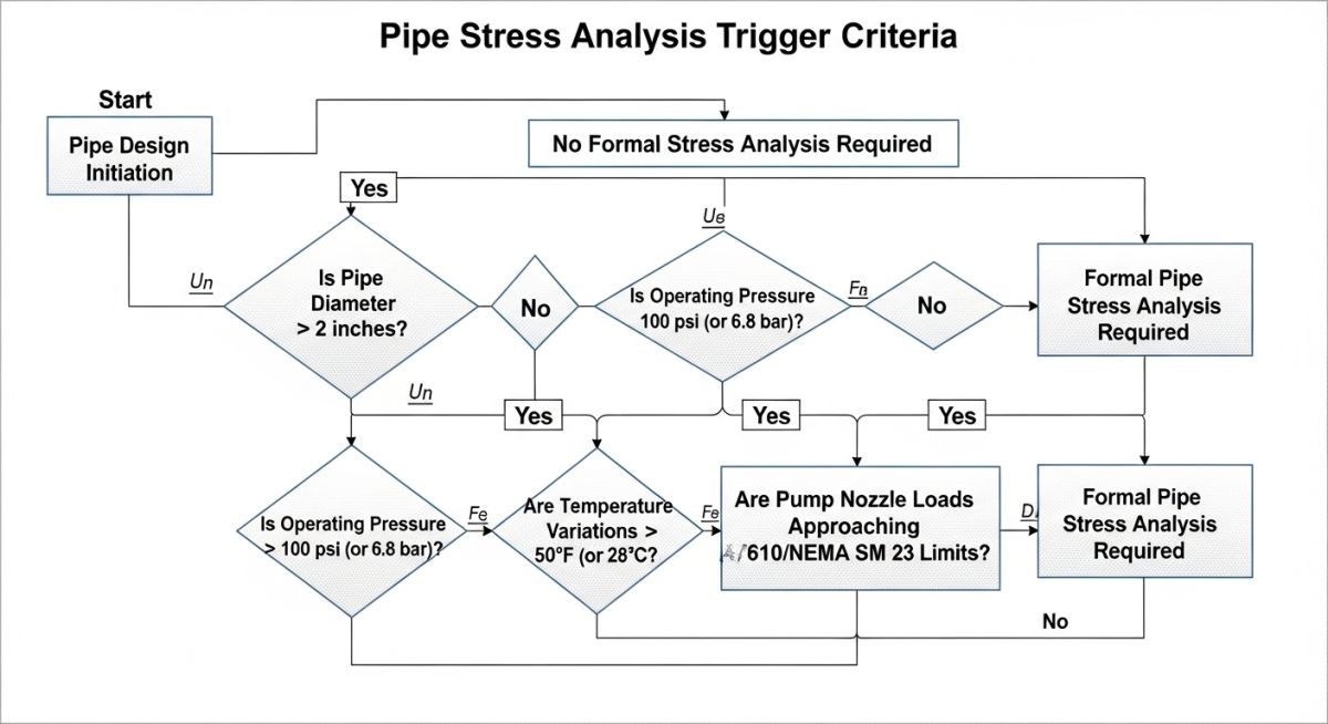
Under ASME B31.3, Paragraph 319.2.1, the designer must analyze piping systems for displacement stress range unless they meet specific simplified criteria. If your cold water system connects to sensitive equipment, undergoes temperature variations greater than 25°C (50°F), or is subject to external movements (such as soil settlement in buried pump station headers), a formal computer-aided analysis using software like CAESAR II is required to demonstrate compliance.
The table below outlines the standard engineering screening thresholds I use to determine whether a cold water piping system requires a formal computer-aided stress analysis or if a simplified visual/manual check is sufficient.
| Nominal Pipe Size (NPS) | Connection Type | Design Temp Range | Analysis Requirement | Applicable Code |
|---|---|---|---|---|
| NPS 2 and smaller | Utility / General | 0°C to 40°C | Visual inspection & standard support spans | ASME B31.9 |
| NPS 3 to NPS 8 | Static Equipment | -5°C to 50°C | Simplified manual calculations (guided cantilever) | ASME B31.3 |
| NPS 3 to NPS 8 | Rotating Equipment (Pumps) | -5°C to 50°C | Formal computer analysis (CAESAR II) recommended | ASME B31.3 / API 610 |
| NPS 10 and larger | Any Connection | All ranges | Mandatory formal computer stress analysis | ASME B31.3 |
This matrix maps the critical technical entities, physical parameters, and standard references that must be integrated into your pipe stress analysis workflow for cold water systems.
| Technical Entity | Structural Acronym | Physical Parameter | Standard Reference |
|---|---|---|---|
| Allowable Stress Range | SA | Material yield and tensile strength limits | ASME B31.3 Paragraph 302.3.5 |
| Pump Nozzle Load Limits | PNL | Forces (Fx, Fy, Fz) and Moments (Mx, My, Mz) | API 610 Table 5 / ISO 5199 |
| Hydraulic Transient Force | HTF | Unbalanced dynamic surge force (water hammer) | ASME B31.3 Paragraph 301.5 |
| Seismic Design Category | SDC | Horizontal and vertical acceleration coefficients | ASCE 7 / IBC Chapter 16 |
Key Criteria Mandating Pipe Stress Analysis for Cold Water Piping
Pump Station Piping Verification: The field validation process used to confirm that physical piping layouts, support configurations, and equipment connections match the design assumptions of the stress profile under ASME B31.3.
Before signing off on any cold water pump station design, I walk through this verification checklist. It ensures that the physical realities of the field match the mathematical assumptions made in our stress models.
-
Pump Nozzle Alignment: Verify that the piping is aligned to the pump nozzles without using external force (pulling or winching) to make the connection.
-
First Support Location: Ensure the first piping support (usually a spring hanger or adjustable base elbow) is placed as close to the pump nozzle as physically possible to minimize deadweight transfer.
-
Expansion Joint Tie-Rods: Confirm that tie-rods on rubber expansion joints are adjusted correctly to limit lateral movement while preventing axial blowout under pressure.
-
Structural Anchor Integrity: Check that structural anchors on the piping header are securely bolted to the concrete foundation to isolate the pump station from external pipeline movements.
-
Water Hammer Mitigation: Verify that surge tanks, air release valves, or slow-closing check valves are installed and match the transient analysis model.
Field Case Study: Real-World Application
At a municipal water treatment plant in Ohio, a newly commissioned high-service pump station experienced repeated flange leaks and severe casing vibration on three 24-inch cold water discharge lines. The design team had bypassed formal pipe stress analysis because the operating temperature was a constant 15°C (59°F). Within three months of operation, the drive-end bearings of the primary pump failed due to shaft misalignment caused by excessive nozzle loads.
I was brought in to perform a retrospective CAESAR II stress analysis. We discovered that the 24-inch piping header, which ran 60 meters outdoors before entering the ground, was expanding due to solar radiation during the day. This expansion, combined with the weight of the water-filled pipe and the lack of an anchor between the header and the pump, transferred a bending moment of 45,000 N-m to the pump discharge nozzle. This was more than 350% of the allowable limit specified by API 610.
To resolve the issue, we installed a concrete anchor block right before the piping entered the pump station building, added adjustable spring supports under the discharge elbows, and installed a tied rubber expansion joint. The nozzle loads dropped to within 40% of the allowable limits, and the pump has operated without vibration or leaks for over five years.
This case study highlights why relying on “rules of thumb” or ignoring stress analysis for cold water systems is a major risk. A small investment in a formal stress analysis during the design phase would have saved the municipality hundreds of thousands of dollars in equipment repairs and downtime.
Frequently Asked Engineering Questions
Why is pipe stress analysis required for cold water piping if there is no thermal expansion?
What is the threshold pipe size where stress analysis becomes mandatory?
How does water hammer affect the structural design of cold water piping?
Can I use rubber expansion joints instead of doing a stress analysis?
Which ASME code governs cold water piping at pump stations?
How do environmental temperature changes affect buried cold water lines?
===EOF===
Complete Course on
Piping Engineering
Check Now
Key Features
- 125+ Hours Content
- 500+ Recorded Lectures
- 20+ Years Exp.
- Lifetime Access
Coverage
- Codes & Standards
- Layouts & Design
- Material Eng.
- Stress Analysis