
How Civil Engineers in Oil and Gas Design Resilient Infrastructure
Over my 20-year career in industrial piping and structural design, I have often seen people overlook the massive contribution of civil engineers in the energy sector. Many assume our world is purely about mechanical piping, chemical reactors, and electrical grids. But let me tell you this: not a single piece of heavy process equipment, offshore jacket, or cross-country pipeline can function without the structural backbone designed by civil engineers.
In my experience, the transition from standard commercial civil engineering to the oil and gas sector is a massive leap in complexity. We are not just dealing with static dead loads and standard wind forces. We are designing foundations for massive reciprocating compressors that generate continuous dynamic vibrations, offshore platforms subjected to extreme wave impacts, and blast-resistant control rooms engineered to withstand accidental hydrocarbon explosions.
Key Engineering Takeaways
- Understand the critical role of soil-structure interaction under dynamic loading conditions.
- Learn how offshore jacket structures are designed to withstand environmental fatigue.
- Master the application of blast-resistant design principles for petrochemical control buildings.
- Discover the structural life extension methodologies used for aging energy assets.
Why Civil Engineers in Oil and Gas Matter
Structural Integrity Management: The systematic application of engineering principles to ensure that offshore jackets, foundations, and blast-resistant buildings remain safe and functional throughout their operational lifecycle under API RP 2SIM guidelines.
In the oil and gas sector, civil and structural engineers are tasked with ensuring the absolute stability of assets worth billions of dollars. This work spans across three primary domains: upstream (offshore platforms and drilling templates), midstream (pipeline supports, terminals, and storage tanks), and downstream (refineries, petrochemical plants, and LNG export facilities).
1. Offshore Structural Design (API RP 2A-WSD)
Offshore jacket platforms are subjected to continuous cyclic loading from waves, wind, currents, and operational payloads. Civil engineers use advanced finite element analysis (FEA) to design steel space frames that can withstand these forces. The design must account for fatigue life, typically calculated using S-N curves and fracture mechanics.
The structural design process involves calculating the environmental forces using wave theories such as Stokes’ Fifth-Order Wave Theory. The total wave force on a cylindrical structural member is determined using Morison’s Equation:
Where:
– F is the total wave force per unit length.
– F_D is the drag force and F_I is the inertia force.
– C_D and C_M are the drag and inertia coefficients, respectively.
– rho is the density of seawater.
– D is the member diameter.
– u is the horizontal water particle velocity.
– du/dt is the local water particle acceleration.
2. Dynamic Foundation Design for Heavy Rotary Equipment
One of the most challenging tasks I have faced is designing foundations for massive rotating machinery, such as gas turbines and reciprocating compressors. These machines generate dynamic forces that can cause severe resonance if the foundation’s natural frequency matches the operating frequency of the machine.
According to ACI 351.3R, the natural frequency (f_n) of the foundation-soil system must be kept at least 20% away from the operating frequency of the machine (f_o) to avoid resonance. The simplified natural frequency of a block foundation can be expressed as:
Where:
– k is the dynamic stiffness of the soil-foundation interface.
– m is the total mass of the foundation block plus the machine payload.
To control vibrations, we typically design the foundation block mass to be at least 3 to 5 times the mass of the reciprocating machine.
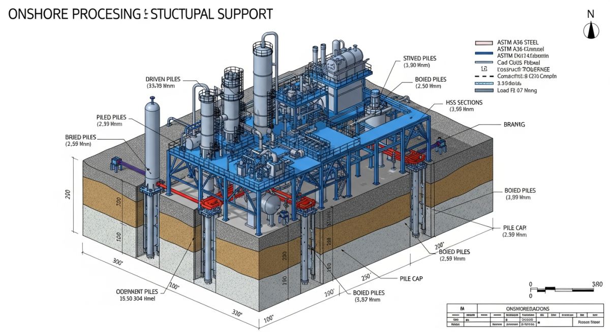
3. Blast-Resistant Design for Control Rooms
In petrochemical facilities, control rooms and occupied buildings must be designed to protect personnel from potential vapor cloud explosions (VCE). Civil engineers utilize the ASCE Design of Blast-Resistant Buildings in Petrochemical Facilities guidelines.
The design involves applying a dynamic overpressure-time history to the structural elements. Instead of designing for elastic behavior, we allow the structural steel and reinforced concrete to undergo plastic deformation (ductile design), utilizing ductility ratios (mu) and peak rotation limits (theta) to absorb the blast energy safely.
| Load Case | Description | Primary Load Components | Allowable Stress Factor |
|---|---|---|---|
| Case 1: Operating | Normal operating conditions with 1-year environmental return loads. | Dead Load + Live Load + Operating Thermal + 1-Yr Wind/Wave | 1.00 (Basic Allowable) |
| Case 2: Extreme Environmental | Design storm conditions with 100-year environmental return loads. | Dead Load + Live Load + 100-Yr Wind/Wave/Current | 1.33 (One-third increase) |
| Case 3: Seismic (DLE) | Difference Level Earthquake event for structural safety. | Dead Load + Operating Live Load + Seismic Inertial Forces | 1.70 (Near Yield Limit) |
| Case 4: Accidental / Blast | Hydrocarbon explosion or vessel impact scenario. | Dead Load + Live Load + Peak Blast Overpressure | Plastic Limit State (Ductile) |
| Entity / Acronym | Technical Definition | Physical Parameter / Metric | Standard Reference |
|---|---|---|---|
| SSI | Soil-Structure Interaction; the mutual influence of soil behavior on structural response. | Dynamic Shear Modulus (G), Poisson’s Ratio (v) | ISO 19901-4 |
| VCE | Vapor Cloud Explosion; rapid combustion of hydrocarbon gas clouds. | Peak Overpressure (psi/bar), Impulse (psi-ms) | ASCE Blast Design |
| S-N Curve | Stress vs. Number of cycles curve used to predict fatigue failure. | Hot Spot Stress Range (Delta Sigma), Cycles (N) | API RP 2A-WSD |
| FND Block | Massive concrete block foundation designed for dynamic machinery. | Mass Ratio (Fnd/Machinery > 3.0), Amplitude (< 0.05 mm) | ACI 351.3R |
Core Challenges for Civil Engineers in Oil and Gas
Geotechnical Site Characterization: The comprehensive evaluation of soil-structure interaction, dynamic soil properties, and marine geology required to design stable foundations for heavy process modules in accordance with ISO 19901-4.
Execution in the field requires rigorous quality control. Below is the engineering checklist I have developed over years of managing site installations for heavy foundations and structural steel alignments.
Foundation & Structural Alignment Field Checklist
Confirm that the actual field soil shear wave velocity (Vs) matches the design assumptions in the dynamic foundation analysis report.
Verify anchor bolt coordinates and projections using high-precision total station surveying. Tolerance must be within +/- 2mm of the mechanical equipment drawing.
Ensure epoxy grout is mixed and poured within the specified temperature window. Check for 100% contact area (no voids) under the equipment baseplate using hammer testing.
Verify that all high-strength structural bolts (ASTM F3125) are tensioned using the turn-of-nut method or calibrated wrench method per AISC specifications.
For marine and underground structures, verify electrical continuity of sacrificial anodes or impressed current systems to prevent localized corrosion.
Field Case Study: Real-World Application
The Problem: Excessive Vibration in a 120-Ton Gas Compressor Foundation
During the commissioning of a major coastal LNG export terminal, a 120-ton reciprocating gas compressor experienced severe lateral vibrations. The vibration amplitudes at the bearing housing exceeded the allowable limits specified by API 618 (greater than 5.0 mm/s RMS), triggering automatic safety shutdowns.
The original design had assumed a stiff clay profile. However, localized soil softening had occurred due to poor site drainage and water accumulation around the foundation block, reducing the dynamic shear modulus of the soil by 45% and shifting the foundation’s natural frequency directly into the compressor’s operating range (resonance).
The Solution & Engineering Outcome
As the lead structural consultant, I directed a two-phase remediation plan:
- Phase 1: Soil Stabilization via Chemical Grouting. We injected high-density polyurethane grout into the soil matrix surrounding the foundation block to displace water and restore the dynamic shear modulus.
- Phase 2: Retrofitting with Micropiles. We installed eight 150mm diameter steel micropiles through the concrete block into the deeper, competent sand layer to transfer dynamic loads and shift the natural frequency.
Outcome: The natural frequency of the foundation-soil system was successfully shifted from 12.5 Hz to 18.2 Hz, well away from the compressor’s operating frequency of 10.0 Hz. Vibration amplitudes dropped to 1.2 mm/s RMS, allowing the plant to operate at full capacity without further downtime.
Direct Recommendation: Always design surface drainage systems to divert water away from heavy dynamic foundations. Water ingress is the single most common cause of dynamic soil stiffness degradation in coastal petrochemical facilities.
Frequently Asked Engineering Questions
What is the primary difference between onshore and offshore civil engineering?
How do civil engineers design structures to resist explosions?
Why is the mass ratio of a dynamic foundation so important?
What codes govern pipeline support design?
How is structural life extension evaluated for aging platforms?
What is soil liquefaction and how is it mitigated?
===
Complete Course on
Piping Engineering
Check Now
Key Features
- 125+ Hours Content
- 500+ Recorded Lectures
- 20+ Years Exp.
- Lifetime Access
Coverage
- Codes & Standards
- Layouts & Design
- Material Eng.
- Stress Analysis

📚 Recommended Resources: civil engineers in oil and gas
Read these Guides
- 📄 Factor of Safety: Complete Engineering Guide, Formulas, and Design Calculator
- 📄 Brownfield vs Greenfield Oil and Gas Projects: Key Engineering Differences
- 📄 What is a Pipe Anchor? Comprehensive Engineering Guide to Design, Types, and Functions
- 📄 Vibration Sensor: Working, Types, and 2026 Selection Guide