What is a Pressure Control Valve? Types and Applications
Over my 20 years in piping engineering, I have seen many systems fail simply because of poorly specified pressure control valves. I remember a refinery project in 2014 where a sudden pressure surge ruptured a bypass line. The culprit? A misconfigured direct-acting valve that could not handle the transient flow. In this guide, I will share my hands-on experience to help you understand how these valves operate, their primary types, and how to select them for your specific industrial applications.
Key Takeaways
- Understand the core mechanics of pressure regulation and force balance.
- Differentiate between relief, reducing, and bypass valves.
- Learn the key ASME and API standards governing valve selection.
- Discover real-world field troubleshooting techniques.
How Does a Pressure Control Valve Work?
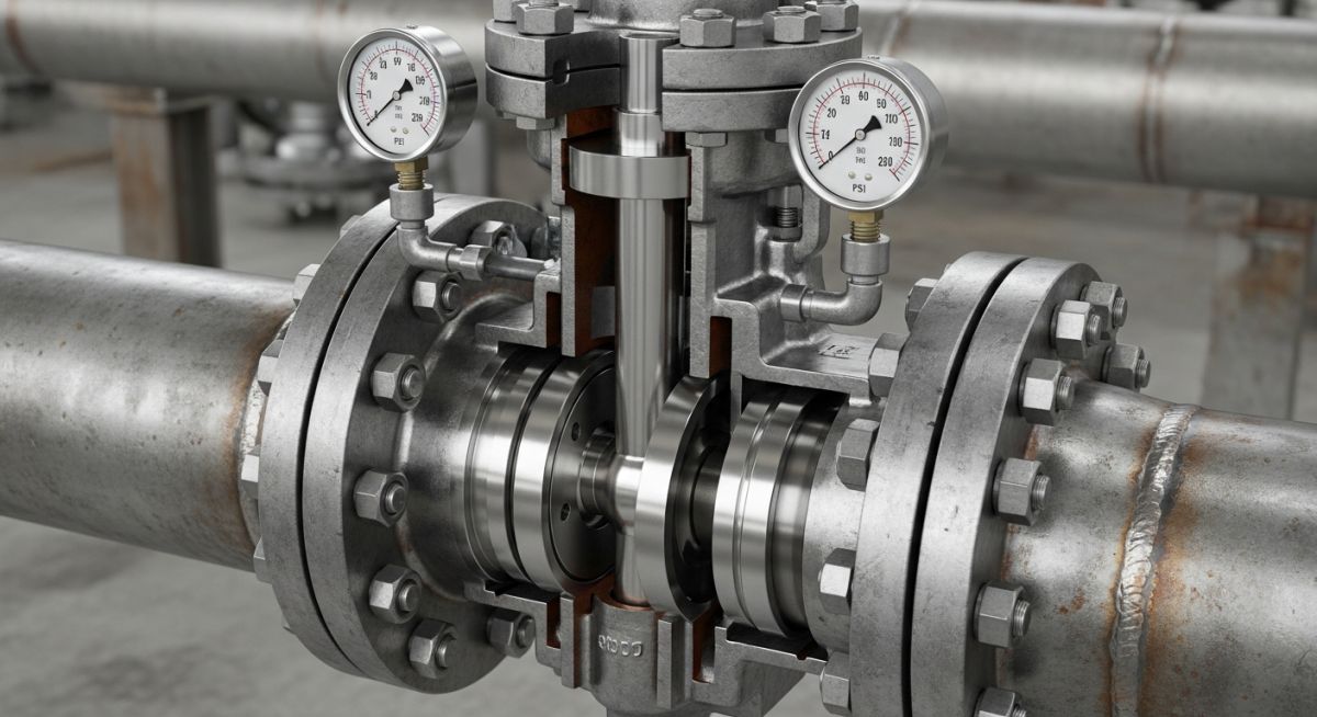
The mechanical equilibrium of a direct-acting pressure control valve is governed by the balance between the spring force and the fluid pressure force. The spring force is calculated as the spring rate multiplied by the compression distance. The fluid force is calculated as the process pressure multiplied by the effective area of the diaphragm or piston. When the fluid force exceeds the spring force, the valve stem moves, altering the flow area.
In my experience, direct-acting valves are highly reliable for simple systems but suffer from “droop”—a drop in controlled pressure as flow increases. For high-capacity systems, pilot-operated valves are preferred. They use a secondary pilot valve to control the main valve, offering much tighter pressure control and higher flow capacities.
Never use a pressure reducing valve as a safety relief valve. While both control pressure, a reducing valve is designed for continuous regulation, whereas a safety relief valve is a certified safety device designed for rapid, full-flow overpressure protection in compliance with ASME Section VIII. Mixing these up can lead to catastrophic system failures.
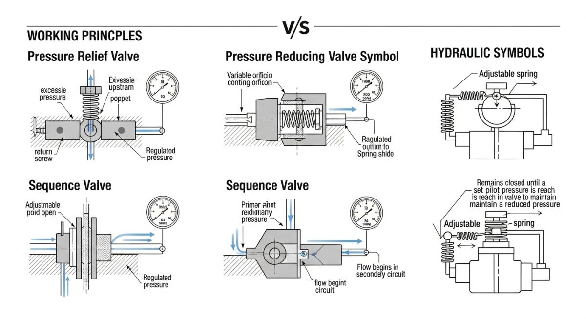
When sizing these valves, engineers must consult API Standard 520 for sizing and selection, and ASME B16.34 for pressure-temperature ratings. Proper sizing prevents issues like cavitation, flashing, and excessive noise.
Selecting the Right Pressure Control Valve Type
To assist in your selection process, I have compiled the following reference tables based on standard industrial practices and manufacturer specifications.
| Valve Type | Primary Function | Governing Code | Typical Set Pressure Range | Common Materials |
|---|---|---|---|---|
| Pressure Relief Valve (PRV) | Overpressure protection | ASME Sec VIII | 15 to 10,000 psig | Carbon Steel, SS316 |
| Pressure Reducing Valve | Downstream pressure control | ASME B31.3 | 5 to 3,000 psig | Cast Iron, Bronze, SS |
| Pressure Bypass Valve | Upstream pressure relief / loop control | API 526 | 10 to 5,000 psig | WCB Carbon Steel, Alloy 20 |
| Entity Name | Common Acronym | Physical Parameter Controlled | Hyperlinked Standard Reference |
|---|---|---|---|
| Pressure Control Valve | PCV | System Fluid Pressure | ASME B16.34 |
| Backpressure Regulator | BPR | Upstream Pressure | API Standard 520 |
| Pilot-Operated Relief Valve | PORV | Overpressure Threshold | API Standard 526 |
Primary Types of Pressure Control Valves
Before putting any pressure control valve into service, a rigorous field verification is required. In my years on site, skipping these basic checks has been the leading cause of premature valve failure and system instability.
Site Verification Checklist
-
Verify flow direction arrow on the valve body matches actual system flow. -
Confirm set pressure matches the approved design datasheet and ASME Section VIII calculations. -
Ensure upstream and downstream pressure gauges are calibrated and installed. -
Check that the bypass line is isolated and leak-tight during initial startup. -
Verify that the spring chamber vent is clear of obstructions and properly oriented.
Field Case Study: Real-World Application
The Problem: Severe Water Hammer and Pressure Spikes
A chemical processing plant experienced severe water hammer and pressure spikes in its cooling water loop. The existing direct-acting bypass valve was sluggish, causing pressure transients that damaged upstream heat exchangers. The system was operating close to its design limit of 150 psig, and the transients frequently tripped the high-pressure alarms.
The Outcome: Fast-Acting Pilot-Operated Solution
I replaced the direct-acting valve with a fast-acting, pilot-operated pressure control valve sized according to API 520. The pilot-operated system responded to pressure changes within milliseconds, completely eliminating the water hammer and stabilizing the loop pressure within 2% of the setpoint.
My direct recommendation for any high-flow system with rapid transient potential is to avoid direct-acting valves. The investment in a high-quality pilot-operated valve pays for itself by protecting downstream assets and preventing costly plant shutdowns.
Frequently Asked Engineering Questions
What is the difference between a pressure relief valve and a pressure safety valve?
How do you prevent valve chatter in a pressure control valve?
What is “droop” in a direct-acting pressure reducing valve?
Can a pressure control valve be installed in any orientation?
How often should a pressure control valve be calibrated?
What causes a pressure control valve to leak constantly?
Complete Course on
Piping Engineering
Check Now
Key Features
- 125+ Hours Content
- 500+ Recorded Lectures
- 20+ Years Exp.
- Lifetime Access
Coverage
- Codes & Standards
- Layouts & Design
- Material Eng.
- Stress Analysis