Table of Contents
What is a Piping Tie-in and Its Schedule?
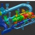
In my 20 years of piping engineering, nothing tests your nerves quite like a complex piping tie-in. You are taking a brand-new, clean, pre-fabricated piping spool and connecting it to an existing, aged, and often dirty operating line. The existing line might be carrying high-pressure hydrocarbons, toxic sour gas, or superheated steam. A single millimeter of misalignment or a minor calculation error in wall thickness can lead to catastrophic field failures, costly shutdown extensions, or severe safety incidents.
When we execute brownfield modifications, the tie-in point is the exact boundary where the old world meets the new. Managing this boundary requires a deep understanding of piping design codes, stress analysis, metallurgy, and construction sequencing. This guide breaks down the engineering principles behind successful tie-ins and details how to construct a robust piping tie-in schedule that keeps your project on track and your field crews safe.
Key Engineering Takeaways
- Understand the fundamental differences between hot tap and cold tie-in execution methodologies.
- Master the ASME B31.3 reinforcement calculations required for branch connections.
- Learn how to structure a comprehensive tie-in schedule to coordinate multi-disciplinary engineering teams.
- Identify field verification techniques to eliminate dimensional errors before shutdown windows.
What are the Main Piping Tie-in Types?
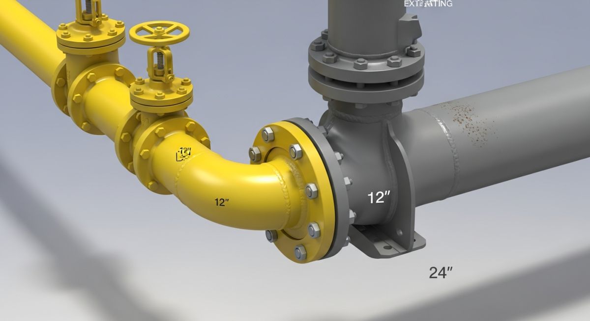
Selecting the correct tie-in method is the first major decision in brownfield piping design. We classify these connections into two primary execution categories: Cold Tie-ins and Hot Taps. Each has distinct design requirements, safety protocols, and cost implications.
1. Cold Tie-ins (Shutdown Required)
A cold tie-in is performed when the existing piping system can be completely depressurized, drained, flushed, and isolated. This is the most common method and is typically scheduled during a planned plant turnaround or shutdown. Because the line is safe and inert, we can perform hot work (cutting and welding) or cold work (installing flanged connections) with minimal risk.
- Welded Cold Tie-in: The existing pipe is cut, beveled, and a new tee or branch connection is welded directly to it. This provides a permanent, leak-free joint but requires extensive non-destructive testing (NDT) such as radiography or ultrasonic testing.
- Flanged Cold Tie-in: If the existing system already has a spare flange or a valve, we can bolt the new piping directly to it. If no flange exists, we cut the pipe, weld a slip-on or weld-neck flange, and then make the connection.
2. Hot Tapping (Under Pressure)
When a plant shutdown is economically unfeasible, we use hot tapping. This technique allows us to connect a new branch line to an existing pipeline while it remains under pressure and in operation. The process involves welding a split-tee fitting or a weldolet to the active run pipe, installing a full-port isolation valve, mounting a specialized hot tapping machine, and cutting a hole through the pipe wall.
In my experience, hot tapping must never be performed on lines containing oxygen, air-hydrocarbon mixtures, or highly reactive chemicals like ethylene oxide or acids that can cause exothermic reactions. Always perform a ultrasonic thickness (UT) check on the existing pipe to ensure sufficient wall thickness exists to support the weld without burn-through.
ASME B31.3 Branch Reinforcement Calculations
When you cut a hole in an existing pipe for a tie-in, you weaken the pressure containment capability of the header pipe. ASME B31.3 Section 304.3.3 dictates that the metal removed by the opening must be compensated for by excess thickness in the header and branch pipes, or by adding a reinforcement pad (re-pad).
The basic area compensation formula is expressed as:
Where:
- d1 = Corroded internal dimension of the branch channel.
- th = Pressure design thickness of the header calculated per ASME B31.3 Section 304.1.2.
- beta = Angle between the branch and the header (typically 90 degrees, making sin(beta) equal to 1).
The available area (Aa) is the sum of the excess thickness in the header (A2), the excess thickness in the branch (A3), and the area of the weld metal (A4). If the sum of these areas is less than the required area (Ar), we must add a reinforcement pad with area (A5) to satisfy the code:
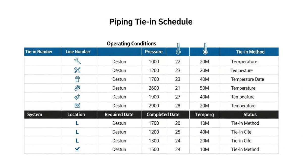
How to Create a Piping Tie-in Schedule?
A piping tie-in schedule is the single source of truth for the construction team. It bridges the gap between the engineering office and the field. Below is a typical engineering template that I use on major petrochemical projects to track and execute tie-ins.
| Tie-in No. | Existing Line No. | New Line No. | Fluid Service | Temp / Press | Tie-in Type | NDT Method | Execution Window |
|---|---|---|---|---|---|---|---|
| TI-001 | 10″-HC-1024-A1A | 6″-HC-2055-A1A | Hydrocarbon Gas | 120°C / 15 barg | Hot Tap (Split Tee) | UT / PT / Hydro | Online (No Shutdown) |
| TI-002 | 8″-HPS-3012-B3A | 4″-HPS-4021-B3A | High Press Steam | 350°C / 42 barg | Cold (Welded Tee) | RT / UT / PWHT | Planned Turnaround |
| TI-003 | 12″-CWR-5004-D1A | 8″-CWR-6012-D1A | Cooling Water Return | 45°C / 4.5 barg | Cold (Flanged) | Visual / PT | Weekend Shutdown |
| TI-004 | 2″-IA-7011-E1A | 1″-IA-8022-E1A | Instrument Air | Ambient / 7 barg | Cold (Threaded) | Bubble Test | Local Isolation |
Technical Mapping & Specifications Matrix
To ensure all engineering disciplines are aligned, we map the core technical entities, structural acronyms, and physical parameters to their respective code references.
| Entity / Acronym | Physical Parameter | Standard Reference | Engineering Requirement |
|---|---|---|---|
| PWHT | Post-Weld Heat Temp | ASME B31.3 Table 331.1.1 | Mandatory for carbon steel wall thickness exceeding 19mm to relieve residual stresses. |
| NDT | Volumetric Integrity | ASME Section V | Radiographic or Ultrasonic testing required to verify weld quality before hydrotest. |
| Hot Tap Fitting | Pressure Rating | API RP 2201 | Must match or exceed the design pressure and temperature of the existing header. |
| Piping Stress | Nozzle Load Limits | API 610 / ASME Sec VIII | Thermal expansion of new line must not overload existing equipment connections. |
How to Verify Tie-ins on Site?
Never trust old “as-built” drawings blindly. In my career, I have seen as-built drawings that were off by several inches because of undocumented field modifications made years prior. Before you release any tie-in spool for fabrication, your design team must physically verify the existing site conditions.
Site Verification & Design Checklist
-
Dimensional Verification: Confirm the exact center-line coordinates (X, Y, Z) and orientation of the existing tie-in point using 3D laser scanning or manual double-triangulation measurements.
-
Ovality and Wall Thickness: Perform ultrasonic thickness (UT) testing around the entire circumference of the existing pipe at the cut line to verify structural integrity and check for internal corrosion.
-
Flange Specification Match: Physically inspect the existing flange face, rating (e.g., Class 150, 300, 600), standard (ASME B16.5), and gasket type (RTJ, Spiral Wound) to ensure the new mating flange matches perfectly.
-
Metallurgy Verification: Perform Positive Material Identification (PMI) on the existing pipe to confirm its material grade (e.g., Carbon Steel A106-B, Stainless Steel 316L) and select the correct welding electrode.
-
Interference and Access Check: Verify that there is sufficient physical clearance for construction tools, welding habitats, rigging equipment, and the hot tap machine if applicable.
Field Case Study: Real-World Application
The Problem: Thermal Expansion and Misalignment
During a major refinery expansion project, we had to tie a new 12-inch stainless steel product line into an existing 16-inch carbon steel header. The existing header operated at 280°C. The original design team relied on 15-year-old as-built drawings to pre-fabricate the entire tie-in spool.
When the construction crew cut the existing line during a tight 48-hour shutdown window, they discovered two major issues: the existing header had sagged by 45mm due to inadequate support, and the actual pipe schedule was Schedule 80, whereas the drawings indicated Schedule 40. The pre-fabricated spool did not fit, and the welding procedures did not match the thicker wall.
The Outcome: Rapid Engineering and Field Modification
We immediately mobilized our stress analysis and welding engineering teams. First, we updated the stress model in CAESAR II to account for the 45mm sag and verified that the nozzle loads on the downstream pump remained within API 610 limits.
Second, we qualified a new welding procedure specification (WPS) on-site to handle the transition joint between the Schedule 40 new spool and the Schedule 80 existing pipe, utilizing a 1:4 taper weld prep per ASME B31.3. The spool was modified on-site, welded, radiographed, and successfully hydrotested within the remaining shutdown window, avoiding a 150,000-per-day delay penalty.
My direct recommendation from this experience is simple: always include a “field-fit weld” (FFW) or “green meat” (typically 100mm to 150mm of extra pipe length) on your tie-in spools. This allows the construction crew to cut the spool to the exact length required on-site, absorbing any dimensional discrepancies in the existing system.
Frequently Asked Engineering Questions
What is the difference between a tie-in and a hot tap?
Why is a “Golden Flange” or “Golden Joint” used in tie-ins?
How do you handle thermal expansion differences at a tie-in point?
What is a tie-in index and how does it relate to the schedule?
What are the minimum wall thickness requirements for hot tapping?
How do you isolate a tie-in point during a cold shutdown?
======
Complete Course on
Piping Engineering
Check Now
Key Features
- 125+ Hours Content
- 500+ Recorded Lectures
- 20+ Years Exp.
- Lifetime Access
Coverage
- Codes & Standards
- Layouts & Design
- Material Eng.
- Stress Analysis

📚 Recommended Resources: Piping Tie-in
Read these Guides
- 📄 Mastering Piping Isometric Drawings: Symbols, Reading, and Software Guide
- 📄 How Buried Pipeline Stress Analysis Coating Factor Impacts Piping Integrity
- 📄 Top Piping Stress Analysis Software Packages for 2026
- 📄 Top Piping Design Software Packages for 2026 | 2D & 3D Modelling Software Packages | Piping Design CAD Tools


Related posts:
![Super duplex stainless steel piping network on an offshore oil drilling platform.]()
Super Duplex Stainless Steel Oil and Gas Piping Design Guide
![Industrial duplex stainless steel piping system in a chemical processing facility.]()
Understanding Duplex Stainless Steel Properties and Industrial Piping Applications
![A welder performing a critical golden joint weld on an industrial steel pipeline.]()
What is a Golden Joint in Piping Systems?
![A collection of different types of industrial pipes classified by material and size on a storage rack.]()
Comprehensive Guide to Types of Pipes and Industrial Classification Systems
![Industrial piping network with digital overlays representing inch-dia and inch-meter engineering calculations.]()
What are Inch-Dia and Inch-Meter in Piping Systems?
![3D finite element stress analysis model of an industrial piping system showing stress distribution.]()
What Causes Piping System Stresses in Industrial Plants?