Table of Contents

Mastering the Types of Lines in Engineering Drawing Standards
In my 20 years of managing piping and instrumentation diagrams (P&IDs) and isometric layouts, I have seen minor drafting errors lead to catastrophic field modifications. A single misplaced hidden line or an incorrectly weighted continuous line can cause a fabrication shop to misinterpret a critical offset. Understanding the exact language of lines is not just a drafting skill; it is a safety requirement.
When we transition from a digital CAD environment to a physical print on a windy construction site, the contrast between line weights is what keeps the project on track. If your lines bleed together or lack clear definition, the field crew will make assumptions. In heavy industries, assumptions are expensive. This guide breaks down the standard line types, their mathematical relationships, and how to apply them to eliminate ambiguity.
Key Takeaways for Field Engineers
- Line weights must maintain a minimum 2:1 contrast ratio between thick and thin lines to remain legible when scaled down.
- Visible object lines always take precedence over hidden and center lines when they overlap on a drawing.
- ASME Y14.2 and ISO 128 are the governing international standards that dictate line widths and spacing.
- Incorrect line patterns on piping isometrics can lead to material procurement errors and costly field reworks.
- CAD layer management must be locked to prevent manual overrides of standard line weights.
Understanding Types of Lines in Engineering Drawing Standards
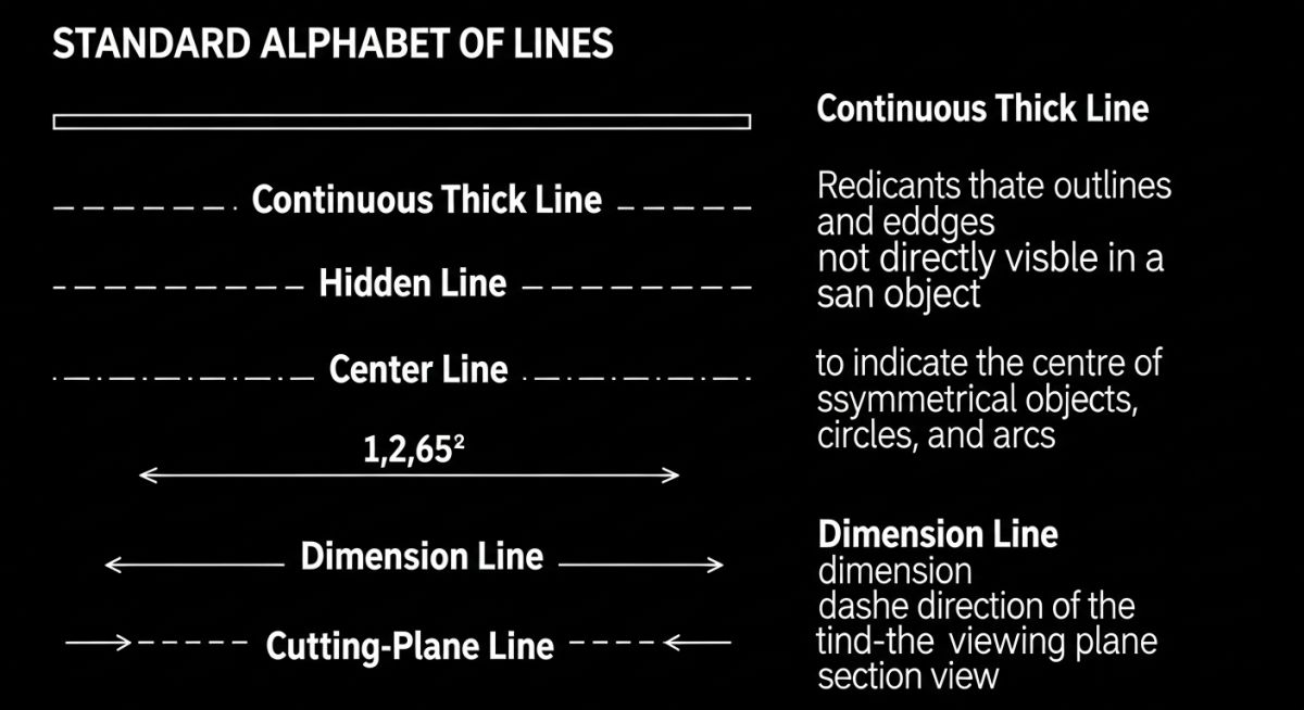
To read a blueprint like a professional, you must understand the “Alphabet of Lines.” Every line on a technical drawing has a specific meaning, dictated by its style, weight, and application. The two primary standards governing these lines are ASME Y14.2 (Line Conventions and Lettering) in North America and ISO 128 internationally.
The Mathematical Logic of Line Contrast
In my experience, the most common drafting failure is poor line contrast. When a drawing is reduced from an A0 size to an A3 size for field use, thin lines can disappear, or thick lines can merge. To prevent this, standards dictate a strict mathematical relationship for line weights:
Contrast Ratio (Rc) = W_thick / W_thin
Where:
– W_thick = Width of thick lines (e.g., visible lines, cutting planes) = 0.5 mm to 0.7 mm
– W_thin = Width of thin lines (e.g., center lines, dimension lines) = 0.25 mm to 0.35 mm
Requirement: Rc >= 2.0
For high-density drawings, the minimum spacing between parallel lines (S_min) must scale with the line width to prevent ink bleeding or pixel merging during digital compression:
S_min >= 2 * W_thick (with an absolute minimum of 0.7 mm on the physical print)
Primary Line Types and Their Functions
Let us examine the core line types that form the foundation of any technical drawing:
- Visible / Object Lines: Thick, continuous lines used to represent the visible edges and contours of an object. These must stand out clearly as the dominant feature of the drawing.
- Hidden Lines: Medium-weight dashed lines (typically 3 mm dashes with 1 mm spaces) representing edges, surfaces, or limit lines that are obscured from view. They are critical for understanding internal geometries without creating a cross-section.
- Center Lines: Thin, alternating long and short dashed lines (typically 20 mm long dashes, 1.5 mm spaces, and 3 mm short dashes) used to indicate axes of symmetry, paths of motion, or center points of circular features.
- Dimension, Extension, and Leader Lines: Thin, continuous lines. Dimension lines terminate with arrowheads to show the extent of a measurement. Extension lines project from the object to keep dimension lines clear of the geometry. Leader lines point directly to a feature for notes or callouts.
- Cutting-Plane / Viewing-Plane Lines: Very thick, heavy dashed lines (either equal dashes or alternating long and double-short dashes) terminated with large arrowheads. These show where an imaginary cut is made to reveal internal details.
The table below outlines the standard line weights and patterns as defined by ASME Y14.2 and ISO 128. These values must be hardcoded into your CAD templates to ensure consistency across all engineering deliverables.
| Line Type | ASME Width (mm) | ISO Width (mm) | CAD Color (Typical) | Primary Application |
|---|---|---|---|---|
| Visible / Object | 0.60 | 0.50 or 0.70 | White/Cyan | Outer boundaries, visible edges, structural profiles |
| Hidden | 0.30 | 0.35 | Yellow | Obscured edges, internal bores, hidden structural ribs |
| Center | 0.30 | 0.25 | Red | Symmetry axes, bolt circles, shaft centers |
| Dimension / Extension | 0.30 | 0.25 | Green | Size definitions, projection lines, leader lines |
| Cutting-Plane | 0.60 | 0.70 | Magenta | Section cuts, viewing plane indications |
| Phantom | 0.30 | 0.25 | Grey | Alternate positions, adjacent parts, future work |
Technical Mapping & Specifications Matrix
This matrix maps specific engineering entities to their required line styles and standard references. Use this as a quick reference during drawing reviews.
| Entity Name | Standard Reference | Primary Function | Visual Pattern | Min. Spacing (mm) |
|---|---|---|---|---|
| Visible Line | ASME Y14.2 | Defines physical boundaries | Continuous Solid | 1.20 |
| Hidden Line | ASME Y14.2 | Shows obscured geometry | Dashed (3mm/1mm) | 0.90 |
| Center Line | ISO 128-20 | Identifies rotational axes | Long-Short-Long | 0.90 |
| Cutting Plane | ASME Y14.2 | Defines section cut path | Thick Dashed / Double Short | 1.50 |
| Phantom Line | ISO 128-20 | Shows adjacent structures | Long-Double Short-Long | 0.90 |
Verifying Types of Lines in Engineering Drawing Reviews
Before signing off on any technical drawing, I run through a strict verification protocol. This checklist ensures that the line work is clean, compliant, and optimized for both digital viewing and physical printing.
Line Quality Verification Steps
Field Case Study: Real-World Application
The Problem: Phantom Line Confusion
During a fast-track refinery expansion, a piping isometric drawing used an incorrect line style for a future expansion bypass line. Instead of a thin phantom line, the draftsman used a solid medium line. The field construction crew interpreted this as an active, immediate-scope piping run, ordering and installing 150 meters of high-alloy piping that was meant for Phase 2.
The Outcome: Rework and Schedule Delay
The error was caught during the pre-commissioning hydrotest walkdown. The redundant piping had to be isolated, blinded, and partially dismantled. This drafting oversight cost the project 84,000 in wasted materials and labor, plus a 4-day delay in the commissioning schedule. We implemented a mandatory CAD template lock to prevent manual overrides of line styles.
My direct recommendation to all engineering managers is to enforce automated CAD standards checking. If a drawing contains non-compliant line weights or styles, it must be automatically rejected by the document control system before it ever reaches the field.
Frequently Asked Engineering Questions
What is the difference between ASME Y14.2 and ISO 128 regarding line types?
Why do visible lines take precedence over hidden lines?
How do I choose the correct line weight for a CAD drawing?
What are phantom lines used for in piping drawings?
Can I use different colors to represent line types on a printed drawing?
What is the standard spacing for hidden line dashes?
Complete Course on
Piping Engineering
Check Now
Key Features
- 125+ Hours Content
- 500+ Recorded Lectures
- 20+ Years Exp.
- Lifetime Access
Coverage
- Codes & Standards
- Layouts & Design
- Material Eng.
- Stress Analysis

📚 Recommended Resources: types of lines in engineering drawing
Read these Guides
🎓 Advanced Training


Related posts:
![Super duplex stainless steel piping network on an offshore oil drilling platform.]()
Super Duplex Stainless Steel Oil and Gas Piping Design Guide
![Industrial duplex stainless steel piping system in a chemical processing facility.]()
Understanding Duplex Stainless Steel Properties and Industrial Piping Applications
![A welder performing a critical golden joint weld on an industrial steel pipeline.]()
What is a Golden Joint in Piping Systems?
![A collection of different types of industrial pipes classified by material and size on a storage rack.]()
Comprehensive Guide to Types of Pipes and Industrial Classification Systems
![Industrial piping network with digital overlays representing inch-dia and inch-meter engineering calculations.]()
What are Inch-Dia and Inch-Meter in Piping Systems?
![3D finite element stress analysis model of an industrial piping system showing stress distribution.]()
What Causes Piping System Stresses in Industrial Plants?