Table of Contents
Comprehensive Guide to Types of Pipes and Industrial Classification Systems
In my 20+ years of hands-on piping engineering experience across petrochemical plants, refineries, and offshore platforms, I have seen how a single misapplied pipe specification can lead to catastrophic field failures. Selecting the correct piping component is not merely about choosing a hollow cylinder; it requires a deep understanding of metallurgy, manufacturing tolerances, and fluid dynamics.
Whether you are designing a high-pressure steam line operating at 540 degrees Celsius or a corrosive chemical transfer system, understanding the distinct characteristics of different piping materials is your first line of defense. This guide breaks down the complex world of industrial piping into structured, actionable engineering knowledge.
- Master the core differences between seamless and welded manufacturing methods.
- Understand how to apply Barlow’s formula for wall thickness verification.
- Learn the specific ASTM and ASME material standards governing industrial piping.
- Identify the operational limits of metallic, non-metallic, and lined piping systems.
How Do We Classify Different Types of Pipes?
Pipe Classification Standards: The systematic categorization of industrial piping utilizes material composition, fabrication techniques, and wall thickness schedules to satisfy the structural integrity requirements of ASME B36.10M and ASME B36.19M.
To design a safe and cost-effective system, we must classify pipes based on three primary criteria: material of construction, manufacturing method, and industrial application. Let us examine these classifications in detail.
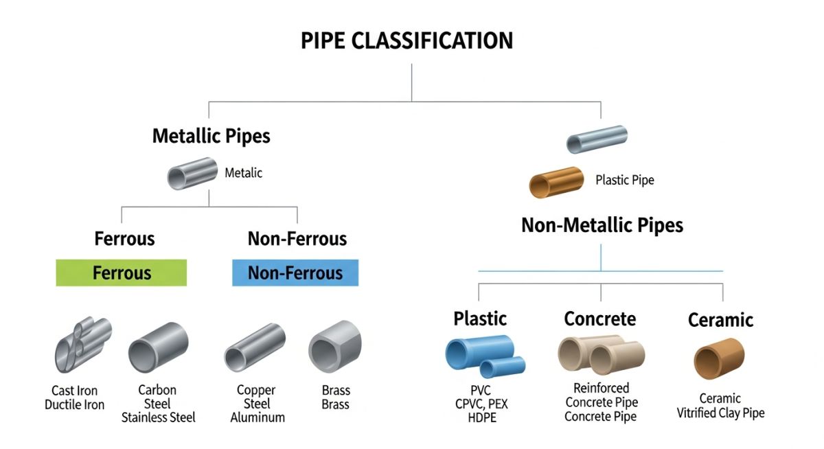
1. Classification by Material of Construction
Piping materials are broadly divided into metallic and non-metallic categories. Metallic piping is further subdivided into ferrous and non-ferrous materials:
- Carbon Steel (CS): The workhorse of industrial piping, typically specified under ASTM A106 Grade B for seamless high-temperature service, and ASTM A53 for utility lines.
- Alloy Steel (AS): Formulated with elements like chromium and molybdenum (e.g., ASTM A335 Grade P11, P22, P91) to withstand high-temperature creep and hydrogen attack in refinery power piping.
- Stainless Steel (SS): Utilized for corrosion resistance and cryogenic services. Common grades include austenitic steels like ASTM A312 TP304L and TP316L.
- Non-Ferrous Metals: Materials such as copper, nickel alloys (Inconel, Monel), and titanium, selected for highly specialized corrosive environments or heat exchanger tubing.
- Non-Metallic Pipes: Includes Thermoplastics (PVC, CPVC, HDPE) and Thermosetting plastics (FRP, GRP), which are immune to electrochemical corrosion but limited by temperature and pressure.
2. Classification by Manufacturing Method
The manufacturing process dictates the joint efficiency factor (E) used in pressure design calculations. The two primary methods are:
- Seamless (SMLS) Pipes: Manufactured by piercing a solid hot billet. Because there is no welded seam, the joint efficiency factor is 1.0, making SMLS pipes the safest choice for high-pressure, high-temperature, and hazardous services.
- Welded Pipes: Fabricated by rolling a steel plate or strip and welding the seam. Common welding techniques include Electric Resistance Welding (ERW), Longitudinal Submerged Arc Welding (LSAW), and Spiral Submerged Arc Welding (SSAW). Welded pipes generally have a joint efficiency factor ranging from 0.85 to 1.0 depending on the level of non-destructive examination (NDE) performed.
Never assume a joint efficiency factor of 1.0 for welded pipes without verifying the NDE requirements in the project specification. Using an incorrect joint factor in your wall thickness calculations can lead to under-designed piping that violates ASME B31.3 safety margins.
Engineering Calculations: Barlow’s Formula
To determine the minimum required wall thickness of a pipe under internal pressure, we utilize Barlow’s Formula as modified by the ASME B31.3 code:
Where:
- t = Minimum design wall thickness (inches or millimeters)
- P = Internal design gauge pressure (psi or MPa)
- D = Outside diameter of the pipe (inches or millimeters)
- S = Allowable stress value for the material at design temperature (psi or MPa)
- E = Quality factor or joint efficiency factor (dimensionless)
- W = Weld joint strength reduction factor (dimensionless, typically 1.0 for moderate temperatures)
- Y = Coefficient of temperature (dimensionless, typically 0.4 for ductile metals below 900 degrees Fahrenheit)
Once the minimum design thickness (t) is calculated, you must add the corrosion allowance (ca) and account for the manufacturer’s mill tolerance (typically 12.5% for seamless steel pipes) to select the final nominal pipe schedule.
What Are the Standard Pipe Material Specifications?
Material Specification Standards: Piping materials are standardized under ASTM and ASME specifications to define chemical composition, mechanical properties, and temperature limits for industrial applications.
The table below outlines the most common metallic piping materials used in industrial plants, along with their corresponding ASTM standards, temperature limits, and typical fluid services.
| Material Class | ASTM Standard | Temperature Range | Typical Service Applications | ASME Code |
|---|---|---|---|---|
| Carbon Steel (High Temp) | ASTM A106 Gr. B | -29°C to 425°C | Steam, condensate, hydrocarbons, utility air | ASME B31.3 |
| Carbon Steel (Low Temp) | ASTM A333 Gr. 6 | -45°C to 343°C | Low-temperature hydrocarbons, cold climates | ASME B31.3 |
| Alloy Steel (Chrome-Moly) | ASTM A335 Gr. P11/P22 | High-pressure superheated steam, hot hydrogen | ASME B31.1 | |
| Austenitic Stainless Steel | ASTM A312 TP316L | -254°C to 815°C | Corrosive chemicals, acids, cryogenic fluids | ASME B31.3 |
| Duplex Stainless Steel | ASTM A790 UNS S31803 | -50°C to 280°C | Produced water, seawater, high-chloride environments | ASME B31.3 |
| Pipe Type | Joint Efficiency (E) | Size Range (NPS) | Dimensional Standard | Primary Advantage |
|---|---|---|---|---|
| Seamless (SMLS) | 1.00 | 1/8″ to 26″ | ASME B36.10M | No weld seam, highest pressure rating |
| Electric Resistance Welded (ERW) | 0.85 | 2″ to 24″ | ASME B36.10M | Cost-effective for medium pressures |
| Submerged Arc Welded (LSAW) | 1.00 (with 100% RT) | 16″ to 60″ | ASME B36.10M | Ideal for large-diameter high-pressure lines |
| High-Density Polyethylene (HDPE) | N/A (Friction Welded) | 1/2″ to 63″ | ASTM F714 | Excellent flexibility, zero corrosion |
How to Verify Types of Pipes on Site?
Site Verification Protocol: Field inspection of piping materials requires systematic verification of mill test reports, physical markings, and dimensional tolerances to prevent installation of non-compliant components.
Before any pipe is welded or installed in the field, quality control inspectors must perform rigorous checks. Below is the exact checklist I use during my site audits to ensure compliance with ASME codes and project specifications.
-
Mill Test Certificate (MTC) Verification: Cross-reference the heat number stamped on the pipe body with the supplied MTC. Ensure chemical composition and mechanical properties match ASTM requirements.
-
Physical Marking Check: Verify that the pipe has continuous stencil markings showing the manufacturer’s name, ASTM standard, grade, size (NPS), wall thickness schedule, and heat number.
-
Dimensional Inspection: Measure the outside diameter (OD), wall thickness, and length using calibrated vernier calipers and ultrasonic thickness gauges. Verify against ASME B36.10M tolerances.
-
Visual Surface Inspection: Inspect the pipe surface for defects such as laminations, cracks, deep pitting, or mechanical gouges. Seamless pipes must be free of longitudinal surface seams.
-
Positive Material Identification (PMI): For alloy and stainless steel pipes, perform PMI testing using a handheld XRF analyzer to confirm the chemical composition before welding.
Field Case Study: Real-World Application
Field Failure Analysis: Forensic engineering investigations of piping failures reveal that incorrect material selection and joint efficiency assumptions directly cause catastrophic pressure boundary breaches.
During a routine startup at a combined-cycle power plant, a 12-inch high-pressure steam line operating at 400°C and 45 bar experienced a sudden, catastrophic longitudinal split. The rupture caused an immediate plant shutdown and significant equipment damage.
Upon forensic investigation, my team discovered that the piping specification called for seamless ASTM A106 Grade B pipe. However, during a previous plant turnaround, a contractor had mistakenly installed an Electric Resistance Welded (ERW) ASTM A53 Grade B pipe in that section. The ERW pipe had a lower joint efficiency factor and was highly susceptible to weld-seam fatigue under cyclic thermal loading, leading to premature failure.
- Replaced the entire failed run with certified seamless ASTM A106 Grade B piping.
- Implemented a mandatory Positive Material Identification (PMI) and ultrasonic thickness testing protocol for all high-pressure steam lines.
- Updated the plant’s procurement specifications to strictly forbid the use of ERW piping in services operating above 200°C or under cyclic thermal conditions.
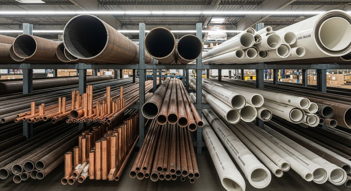
- Established a color-coding system for warehouse storage to prevent the mixing of seamless and welded pipe stocks.
This case study highlights the critical importance of material control and field verification. A simple mix-up in the warehouse between seamless and welded carbon steel pipes resulted in millions of dollars in lost production and repair costs.
What Are the Primary Types of Pipes?
Piping Engineering FAQ: This technical reference addresses critical questions regarding material selection, manufacturing tolerances, and code compliance for industrial piping systems.
What is the difference between a pipe and a tube?
Why is seamless pipe preferred over welded pipe in high-pressure services?
What does “Schedule” mean in pipe specifications?
When should I specify galvanized steel pipes?
What is the mill tolerance for seamless steel pipes?
How do temperature variations affect plastic piping systems?
Complete Course on
Piping Engineering
Check Now
Key Features
- 125+ Hours Content
- 500+ Recorded Lectures
- 20+ Years Exp.
- Lifetime Access
Coverage
- Codes & Standards
- Layouts & Design
- Material Eng.
- Stress Analysis

📚 Recommended Resources: types of pipes
Read these Guides
🎓 Advanced Training


Related posts:
![Super duplex stainless steel piping network on an offshore oil drilling platform.]()
Super Duplex Stainless Steel Oil and Gas Piping Design Guide
![Industrial duplex stainless steel piping system in a chemical processing facility.]()
Understanding Duplex Stainless Steel Properties and Industrial Piping Applications
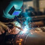
![A welder performing a critical golden joint weld on an industrial steel pipeline.]()
What is a Golden Joint in Piping Systems?
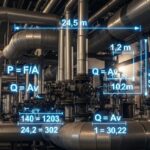
![Industrial piping network with digital overlays representing inch-dia and inch-meter engineering calculations.]()
What are Inch-Dia and Inch-Meter in Piping Systems?
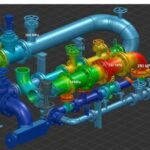
![3D finite element stress analysis model of an industrial piping system showing stress distribution.]()
What Causes Piping System Stresses in Industrial Plants?
![Industrial piping system featuring a large U-shaped pipe expansion loop on an elevated rack.]()
How to Design Pipe Expansion Loops for Piping Systems