Table of Contents
What is Structural Steel Fabrication and How Does It Work?
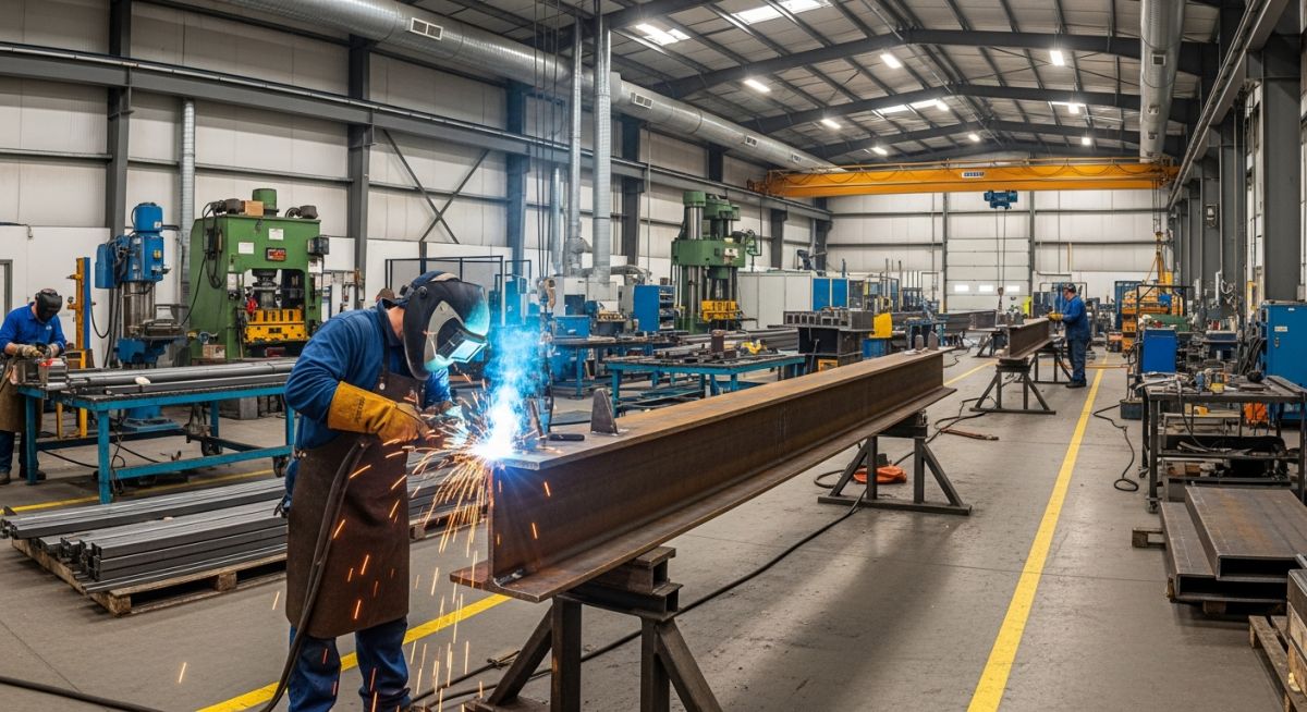
In my 20 years of managing heavy industrial projects, I have seen many structural designs fail not because of poor engineering calculations, but because of a fundamental disconnect between the design office and the fabrication shop floor. Structural steel fabrication is the bridge that turns theoretical blueprints into physical reality. Whether you are erecting a multi-story commercial tower or building a heavy industrial pipe rack, understanding the nuances of this process is what separates a successful project from a costly, delayed disaster.
Every cut, weld, and bolt hole must align with extreme precision. When you are dealing with thousands of tons of steel, a deviation of just a few millimeters can cascade into massive fit-up issues on-site. In this guide, I will take you inside the fabrication shop, breaking down the exact process stages, the engineering standards we live by, and the practical field lessons I have learned along the way.
Key Takeaways
- Code Compliance: All structural fabrication must adhere strictly to AISC 360 for design and AWS D1.1 for welding.
- Precision Detailing: Modern fabrication relies on Tekla or similar BIM software to generate LOD 400 shop drawings.
- Quality Control: Non-destructive testing (NDT) is non-negotiable for high-stress moment connections.
Complete Course on
Piping Engineering
Check Now
Key Features
- 125+ Hours Content
- 500+ Recorded Lectures
- 20+ Years Exp.
- Lifetime Access
Coverage
- Codes & Standards
- Layouts & Design
- Material Eng.
- Stress Analysis
Why is Structural Steel Fabrication Critical for Modern Infrastructure?
[Structural Steel Fabrication Processes]: These specialized manufacturing workflows transform raw mill shapes into high-tolerance structural elements designed to withstand severe seismic and wind loads under AISC and IBC design criteria.
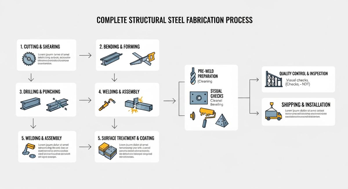
The journey from raw steel to a finished structural frame involves six distinct stages. Each stage requires specialized equipment, certified personnel, and rigorous quality checks.
1. Design and Detailing (LOD 400)
Before a single piece of steel is touched, detailers create highly accurate 3D models using Building Information Modeling (BIM) software. These models define every bolt, weld, gusset plate, and beam dimension. The output is a set of shop drawings and CNC files (DSTV format) that directly drive the automated machinery in the shop.
2. Cutting and Profiling
Raw steel sections (W-shapes, channels, angles, and plates) are cut to length. Modern shops utilize CNC band saws, multi-axis CNC plasma cutters, or high-precision laser cutting systems. These machines read the DSTV files directly, minimizing human error and maximizing material yield.
3. Punching and Drilling
Connection holes must be placed with absolute precision. While punching is faster and more economical for thinner plates (typically under 20 mm), drilling is mandatory for thicker structural members and high-strength applications to prevent micro-cracking around the hole perimeter, which can lead to fatigue failure.
4. Bending and Rolling
For curved architectural elements or specific structural geometries, steel sections are passed through section rollers or heavy-duty press brakes. This process requires careful calculation of the steel’s yield point to avoid over-stressing or buckling the cross-section.
5. Welding and Assembly
This is where the individual components are joined. Fitters assemble the parts using temporary tack welds before certified welders execute the final structural welds. All welding must follow a qualified Welding Procedure Specification (WPS) in accordance with AWS D1.1.
6. Surface Treatment and Coating
To protect the steel from atmospheric corrosion, the fabricated members undergo surface preparation (typically abrasive blasting to SSPC-SP10 “Near-White Metal Blast Cleaning”) followed by the application of primers, epoxy coatings, or hot-dip galvanizing per ASTM A123.
During heavy welding operations, localized heat input causes uneven expansion and contraction of the steel. If you do not manage the welding sequence, the member will warp, bow, or twist out of tolerance. Always enforce backstepping techniques, balanced welding sequences, and the use of proper clamping fixtures to mitigate thermal distortion.
Engineering Calculations: Weld Strength Verification
Let us look at a practical engineering calculation for verifying the design strength of a fillet weld, which is one of the most common connections in structural steel fabrication.
According to AISC 360-16, Chapter J, the nominal strength of a welded joint (Rn) is determined by the limit state of weld shear rupture:
Where:
Fnw = Nominal stress of the weld metal = 0.60 * Fexx * (1.0 + 0.50 * sin^1.5(theta))
Fexx = Electrode classification number (e.g., 70 ksi for E70 electrodes)
theta = Angle of loading measured from the weld longitudinal axis (degrees)
Awe = Effective area of the weld = throat thickness * length of weld
For a standard longitudinal fillet weld (theta = 0 degrees) with a weld size (w) of 5/16 inch (0.3125 in) using E70 electrodes:
Fnw = 0.60 * 70 * (1.0 + 0) = 42.0 ksi
Nominal strength per inch of weld (Rn) = 42.0 * 0.221 * 1.0 = 9.28 kips/inch
Applying the LRFD resistance factor (phi = 0.75):
Applying the ASD safety factor (omega = 2.00):
| ASTM Designation | Common Shapes | Min. Yield Strength (ksi / MPa) | Min. Tensile Strength (ksi / MPa) | Primary Applications |
|---|---|---|---|---|
| ASTM A992 | W-Shapes (I-Beams) | 50 / 345 | 65 / 450 | Main structural framing, columns, and beams |
| ASTM A36 | Angles, Channels, Plates | 36 / 250 | 58-80 / 400-550 | Bracing, gusset plates, secondary members |
| ASTM A500 Grade C | HSS (Hollow Structural Sections) | 50 / 345 (Round) | 62 / 427 | Columns, trusses, space frames |
| ASTM A572 Grade 50 | Plates and Shapes | 50 / 345 | 65 / 450 | High-strength bolted or welded connections |
| Entity / Acronym | Technical Definition | Physical / Design Parameter | Reference Standard |
|---|---|---|---|
| WPS | Welding Procedure Specification | Voltage, travel speed, gas flow rate, preheat temp | AWS D1.1 Clause 5 |
| PQR | Procedure Qualification Record | Destructive test results (tensile, bend, impact) | AWS D1.1 Clause 6 |
| NDT / NDE | Non-Destructive Testing / Evaluation | Ultrasonic (UT), Magnetic Particle (MT), Radiographic (RT) | ASNT SNT-TC-1A |
| Faying Surface | The contact surface between two joining members | Slip coefficient (Class A: 0.30, Class B: 0.50) | RCSC Specification |
How to Perform Structural Steel Fabrication Quality Audits?
[Fabrication Quality Audits]: Systematic quality assurance protocols verify dimensional tolerances, weld integrity, and coating thicknesses against approved shop drawings and AWS D1.1 specifications.
A robust quality audit is the only way to prevent field rework. When I audit a fabrication facility, I look beyond the paperwork. I inspect the physical storage, the calibration dates on the welding machines, and the actual execution of the fit-up. Use this checklist on your next shop visit to ensure compliance.
Shop Audit & Site Verification Checklist
-
Material Traceability: Verify that all raw steel sections have legible heat numbers stamped or painted on them, matching the Mill Test Reports (MTRs) in compliance with AISC 360.
-
Welder Qualifications: Confirm that all welders are certified for the specific positions and processes they are executing, with active continuity logs showing they have welded within the last 6 months.
-
Joint Fit-Up Inspection: Check root openings, bevel angles, and alignment before welding begins. Excessive root openings lead to weld shrinkage and high residual stresses.
-
Consumable Control: Ensure low-hydrogen welding electrodes (e.g., E7018) are stored in holding ovens at a minimum of 250°F (120°C) after opening to prevent moisture absorption and hydrogen-induced cracking.
-
Dimensional Tolerances: Measure overall length, camber, sweep, and bolt hole patterns against the tolerances specified in the AISC Code of Standard Practice (AISC 303).
-
Dry Film Thickness (DFT): Use a calibrated magnetic gauge to verify that the primer and paint coatings meet the specified dry film thickness requirements across multiple test points.
Field Case Study: Real-World Application
The Problem: Lamellar Tearing in Heavy Moment Connections
During the construction of a 45-story commercial tower, ultrasonic testing (UT) revealed subsurface cracking in the column flange plates directly behind heavy, full-penetration groove welds. These welds connected the thick beam flanges to the column. The project was put on hold, threatening millions of dollars in delay penalties. The cracking was identified as lamellar tearing, caused by high localized tensile strains acting in the through-thickness (Z-axis) direction of the column plates, combined with high weld restraint.
As the lead structural consultant, I immediately implemented a multi-step remediation plan:
- Material Replacement: We replaced the remaining highly-restrained column plates with steel specified under ASTM A770, which guarantees minimum through-thickness reduction of area properties, reducing the risk of lamellar tearing.
- Weld Detail Modification: We modified the weld joint details to reduce the volume of weld metal required, thereby reducing the total shrinkage strain. We changed double-bevel joints to single-bevel joints with a backing bar where appropriate.
- Preheating and Buttering: We enforced a strict preheating protocol (minimum 300°F / 150°C) and applied a “buttering” layer of weld metal on the column flange face before making the main connection weld. This buttering layer acted as a ductile cushion, absorbing the shrinkage strains.
Direct Recommendation: When designing heavy moment connections with plates exceeding 1.5 inches (38 mm) in thickness, always evaluate the joint restraint. Specify ASTM A770 steel for members subjected to high through-thickness welding strains, and ensure the fabrication shop uses low-hydrogen consumables with strict preheat controls.
Frequently Asked Engineering Questions
What is the difference between structural steel fabrication and general metal fabrication?
Which welding processes are most commonly used in structural steel fabrication?
How does thermal distortion affect structural steel fabrication tolerances?
What are the surface preparation standards required before painting structural steel?
How do AISC 360 and AWS D1.1 interact during the fabrication process?
Why is Charpy V-Notch (CVN) toughness testing required for certain structural steel components?

📚 Recommended Resources: structural steel fabrication
Read these Guides


Related posts:
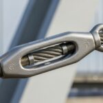
![A heavy-duty stainless steel turnbuckle tensioning a structural cable.]()
What is a Turnbuckle and How to Install It?
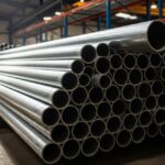
![Stack of newly manufactured galvanized steel pipes in an industrial warehouse]()
Understanding the Galvanized Pipe Meaning in Modern Piping Systems
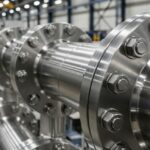
![Industrial Alloy 625 piping components in a manufacturing plant]()
What is Alloy 625? Properties, Grades, and Applications of Alloy 625
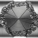
![Close-up of a fractured steel shaft showing metal fatigue beach marks and failure zones.]()
What is Metal Fatigue and How Do Engineers Prevent It?
![Industrial machinery fitted with smart sensors displaying real-time condition-based maintenance data on a digital overlay.]()
What is Condition-Based Maintenance and How Does It Work?
![Comparison of high viscosity honey and low viscosity water pouring to demonstrate fluid resistance]()
Understanding Newton's Law of Viscosity and Key Fluid Flow Factors