Table of Contents
How to Optimize Small-bore Piping Design and Support Systems
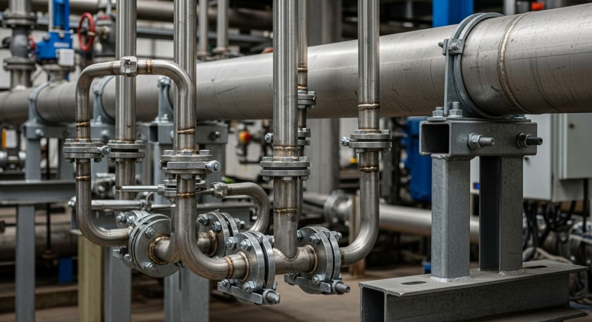
In my 20 years of troubleshooting piping systems in petrochemical plants, I have noticed a recurring theme: major plant shutdowns are rarely caused by the failure of a massive 24-inch header. Instead, they are almost always triggered by a tiny, overlooked 1-inch branch connection that sheared off due to high-cycle fatigue. Small-bore piping is often treated as an afterthought, routed in the field without formal stress analysis. This is a recipe for disaster. I want to share the exact design and supporting strategies I use to ensure these small-bore lines survive the harshest operating conditions.
Key Takeaways
- Understand the critical threshold of Nominal Pipe Size (NPS) 2 and smaller as the definition of small-bore piping.
- Learn how to calculate and apply rigid support spans to shift natural frequencies away from excitation zones.
- Discover the correct implementation of branch connection reinforcements to eliminate fatigue cracking.
Complete Course on
Piping Engineering
Check Now
Key Features
- 125+ Hours Content
- 500+ Recorded Lectures
- 20+ Years Exp.
- Lifetime Access
Coverage
- Codes & Standards
- Layouts & Design
- Material Eng.
- Stress Analysis
Key Principles of Small-bore Piping Design
Small-bore piping systems, typically classified as NPS 2 and smaller, possess low structural stiffness. When connected to high-energy run pipes or rotating equipment like reciprocating compressors and pumps, they become highly susceptible to mechanical excitation. The primary objective in small-bore piping design is to maximize the natural frequency of the system to avoid resonance with the excitation frequencies of the connected equipment.
Calculating Natural Frequency and Support Spans
To prevent resonance, we design the piping system such that its fundamental natural frequency is well above the excitation frequency of the system (typically aiming for a minimum of 4 to 5 Hz above the running speed of rotating equipment, or a default minimum of 31 Hz for general plant piping).
The natural frequency (f) of a straight pipe span can be estimated using the classical beam formula:
Where:
– f = Fundamental natural frequency (Hz)
– C = Support condition constant (e.g., 9.87 for simply supported, 22.4 for fixed-fixed)
– pi = 3.1416
– E = Modulus of elasticity of the pipe material (psi or Pa)
– I = Area moment of inertia of the pipe cross-section (in^4 or m^4)
– w = Uniformly distributed weight of the pipe, including fluid and insulation (lbs/in or kg/m)
– L = Span length between supports (in or m)
From this relationship, it is clear that the span length (L) has a massive impact on the natural frequency. Reducing the span length by half increases the natural frequency by a factor of four. This is why proper spacing of rigid supports is the most effective tool we have in small-bore piping design.
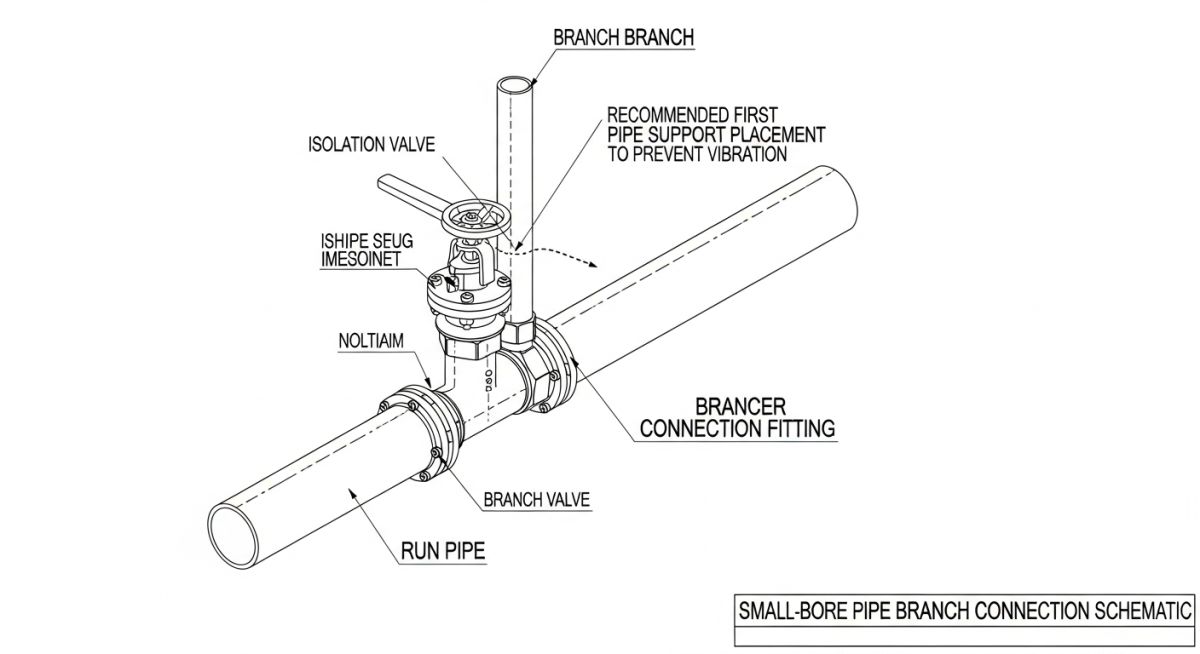
Branch Connection Vulnerabilities
The connection point between a large-bore run pipe and a small-bore branch is the most common location for mechanical failure. This is due to the geometric discontinuity which acts as a stress riser. Under cyclic loading from vibration or thermal cycling, fatigue cracks initiate at the crotch of the branch connection. To mitigate this, I highly recommend using integrally reinforced forged branch outlets (such as weldolets or sweepolets) rather than simple stub-ins or threadolets, especially in high-vibration services.
For detailed design requirements, engineers must refer to ASME B31.3 Process Piping and ASME B31.1 Power Piping codes, which outline stress intensification factors (SIFs) for various branch configurations.
The table below provides the maximum recommended spacing between supports for horizontal carbon steel and stainless steel small-bore piping. These values are calculated to limit sag and maintain a high natural frequency, preventing vibration-induced fatigue.
| Nominal Pipe Size (NPS) | Schedule / Wall Thickness | Water Service Max Span (ft) | Gas/Vapor Service Max Span (ft) | Recommended Support Type |
|---|---|---|---|---|
| 1/2 inch | Sch 80 | 5.0 | 6.0 | Rigid Restraint / Guide |
| 3/4 inch | Sch 80 | 5.5 | 6.5 | Rigid Restraint / Guide |
| 1 inch | Sch 80 / Sch 160 | 6.0 | 7.5 | Rigid Restraint / Guide |
| 1-1/2 inch | Sch 40 / Sch 80 | 7.5 | 9.0 | Rigid Restraint / Guide |
| 2 inch | Sch 40 / Sch 80 | 8.5 | 10.5 | Rigid Restraint / Guide |
This matrix maps common small-bore piping components to their primary failure modes, design solutions, and relevant industry standards.
| Component Type | Primary Failure Mode | Design Solution | Code Reference |
|---|---|---|---|
| Threaded Joints | Fatigue at thread root, leakage | Replace with socket-welded or butt-welded joints in cyclic service | ASME B31.3 Cl. 314 |
| Vents & Drains | Vibration-induced cantilever failure | Install two-plane bracing, minimize valve overhang weight | Energy Institute Guidelines |
| Control Valve Bypass | Acoustic induced vibration (AIV) | Increase pipe wall thickness, install downstream silencers | API RP 521 / ASME B31.3 |
| Thermowells | Vortex shedding resonance | Perform wake frequency calculations, shorten insertion length | ASME PTC 19.3 TW |
Field Checklist for Small-bore Piping Design
Before any plant startup, I always perform a physical walkdown of the small-bore lines. Field routing often deviates from the original design drawings, which can introduce unexpected vulnerabilities. Use this checklist during your next site walkdown to verify the integrity of your small-bore piping installations.
Pre-Commissioning Walkdown Checklist
-
Verify Support Spacing: Ensure that no horizontal span exceeds the maximum limits specified in the design standards. Pay close attention to spans near elbows and concentrated masses like valves.
-
Inspect Branch Connections: Confirm that branch connections on vibrating lines (e.g., compressor discharge) are reinforced with integrally reinforced forged fittings rather than simple stub-ins.
-
Check Valve Bracing: Verify that heavy valves on small-bore lines are supported independently or braced to prevent cantilevered bending stresses on the branch connection.
-
Assess Thermal Expansion Gaps: Ensure that guides and anchors allow for calculated thermal expansion without binding, which could buckle the small-bore pipe.
-
Examine Tubing Transitions: Check that transitions from rigid piping to flexible tubing are properly supported to prevent fatigue at the fitting interface.
Field Case Study: Real-World Application
The Problem: Repeated Fatigue Failures on a Compressor Bypass Line
At a major natural gas processing plant, a 1-inch bypass line connected to a reciprocating compressor discharge header experienced three consecutive fatigue failures over a six-month period. Each failure occurred at the weld joint between the 1-inch sockolet and the 12-inch run pipe. The plant suffered unscheduled shutdowns, costing thousands of dollars per hour. The original installation relied on field-routed piping with standard support spans and no dynamic bracing.
I was called in to analyze the system. We performed a vibration study and found that the compressor’s operating frequency (22 Hz) was in direct resonance with the natural frequency of the unsupported 1-inch bypass line (24 Hz).
To resolve this, we implemented the following design modifications:
- Replaced the sockolet with a sweepolet to reduce the stress concentration factor at the branch connection.
- Installed a rigid, two-plane brace from the 12-inch run pipe to the 1-inch bypass line, effectively tying their movements together and eliminating relative displacement.
- Shortened the unsupported span length near the bypass valve, shifting the natural frequency of the small-bore line to 58 Hz, well clear of the compressor’s excitation range.
Following these modifications, vibration levels dropped by over 85%, and the line has operated without a single failure for over five years. This case highlights why proper small-bore piping design and rigid bracing are necessary for plant reliability.
Frequently Asked Engineering Questions
What is the maximum allowable unsupported span for a 1-inch schedule 80 pipe?
Why are socket-welded joints preferred over threaded joints in small-bore piping?
How do you design supports for small-bore piping connected to high-temperature headers?
What is the purpose of a 1/16-inch gap in socket weld fittings?
When should gusset plates be used on branch connections?
How does acoustic-induced vibration (AIV) affect small-bore piping?

📚 Recommended Resources: small-bore piping design
Read these Guides


Related posts:
![Comparison of high viscosity honey and low viscosity water pouring to demonstrate fluid resistance]()
Understanding Newton's Law of Viscosity and Key Fluid Flow Factors
![A puddle flange installed on a PVC pipe embedded in a concrete wall cross-section]()
What is a Puddle Flange? Types, Applications, and Key Advantages
![Chemical injection system administering corrosion inhibitors to a steel pipeline in an oil and gas facility.]()
Comprehensive Guide to Corrosion Inhibitors in the Oil and Gas Industry
![A metallic two-hole pipe strap securing a copper pipe to a wooden wall beam.]()
What is a Pipe Strap? Its Types, Importance, Materials, Applications
![Heavy-duty vertical pipe support riser clamps installed on steel piping through concrete floors.]()
How to Design and Install Vertical Pipe Support Systems
![Industrial piping system suspended from a ceiling using various types of pipe hanger supports.]()
How to Select and Design Pipe Hanger Supports for Industrial Piping