Brownfield vs Greenfield Oil and Gas Projects: Key Engineering Differences
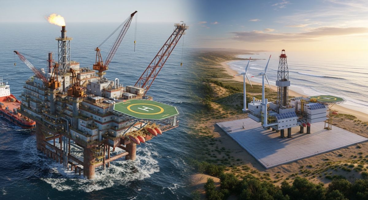
In my 20+ years of piping engineering, I have stood on both sides of the fence. I have walked into live, high-pressure hydrocarbon facilities with a laser scanner in hand, trying to figure out how to squeeze a new 12-inch bypass line into a congested pipe rack. I have also stood in empty deserts and offshore blocks with nothing but a blank plot plan and the freedom to design a facility from scratch. The engineering mindsets required for these two execution models are completely different.
While greenfield projects offer the luxury of optimized layouts and standardized modular designs, they demand massive capital investment and long-term schedule commitments. On the other hand, brownfield projects present a minefield of operational hazards, undocumented “as-built” discrepancies, and complex tie-in challenges, but they offer faster paths to first oil or gas. Understanding these differences is not just an academic exercise; it is a critical requirement for project managers, piping designers, and asset integrity engineers who must deliver these projects safely, on time, and within budget.
Key Engineering Takeaways
- Dimensional Control: Brownfield engineering relies heavily on 3D laser scanning (LiDAR) to mitigate the risks of undocumented field modifications, whereas greenfield engineering relies on standardized coordinate systems and civil site grading.
- Safety and SIMOPS: Brownfield execution requires managing Simultaneous Operations (SIMOPS) and hot work permits in live hydrocarbon environments, demanding rigorous risk assessments under API RP 750.
- Piping Tie-Ins: Integrating new piping into existing systems requires detailed hot tapping calculations and stress analysis governed by ASME B31.3.
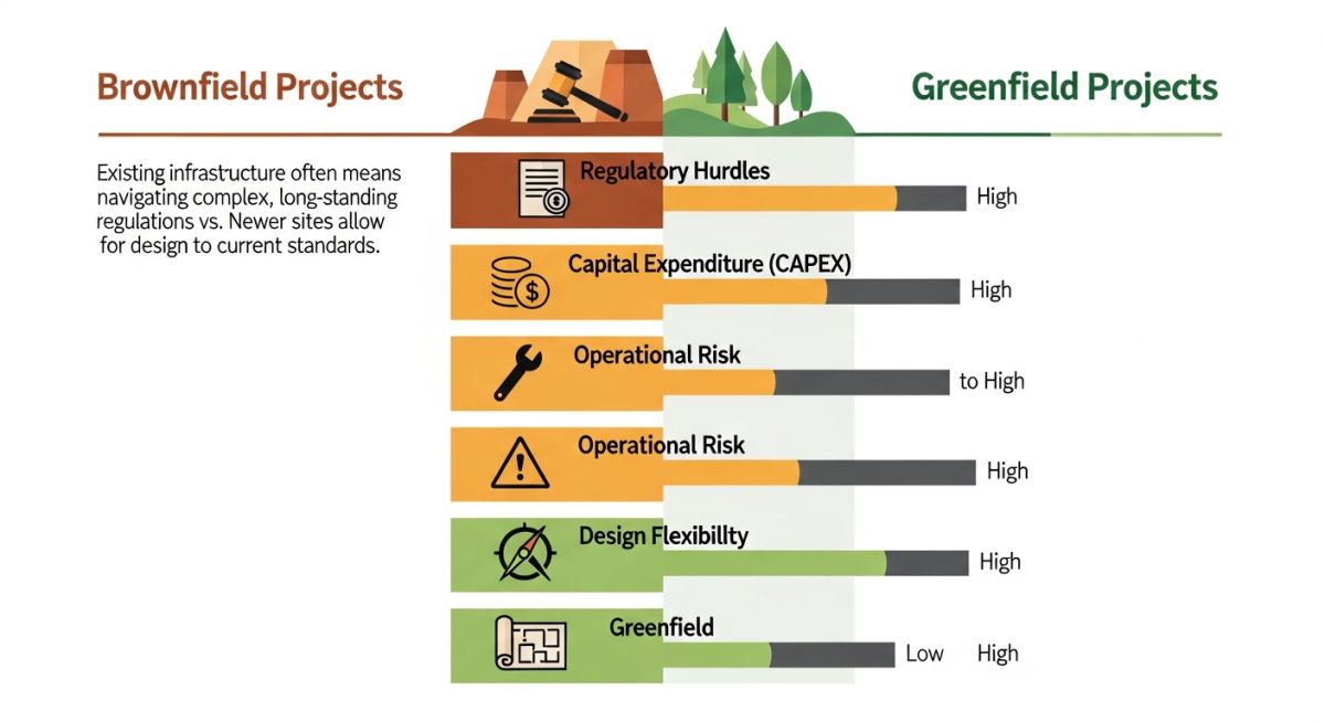
- Capital Efficiency: Greenfield projects carry high upfront CAPEX but lower operational risks, while brownfield projects have lower initial CAPEX but highly unpredictable contingency costs.
- Regulatory Compliance: Brownfield modifications must align with existing environmental permits and facility design bases, whereas greenfield projects must navigate complex environmental impact assessments (EIAs) from scratch.
Analyzing Brownfield vs Greenfield Oil and Gas Design Challenges
When designing a greenfield facility, the engineering team starts with a clean slate. The process design flow dictates the plot plan. We can optimize pipe rack routing, ensure generous maintenance access around control valves, and design foundations based on fresh geotechnical data. The primary challenge is managing the sheer scale of the project and ensuring that the interfaces between different engineering disciplines—process, piping, civil, structural, and instrumentation—are seamlessly coordinated.
In contrast, brownfield design is an exercise in compromise and precision. You are forced to work within the physical constraints of an existing asset. The original “as-built” drawings are almost always inaccurate due to years of undocumented field modifications, repairs, and structural settling. Therefore, the first step in any brownfield piping project is not drafting, but dimensional verification.
Dimensional Control and 3D Laser Scanning
In my practice, I do not trust old paper drawings. We utilize 3D laser scanning (LiDAR) to generate a highly accurate point cloud of the existing facility. This point cloud is then imported into our 3D modeling software (such as Aveva PDMS or Intergraph Smart 3D). This allows us to design new piping runs, supports, and equipment foundations with millimeter-level accuracy, drastically reducing the risk of costly field rework during construction.
Piping Stress Analysis and Tie-In Design
Piping tie-ins are the critical touchpoints where the new brownfield piping meets the existing system. This requires careful stress analysis. The existing piping has already undergone thermal cycles, structural settlement, and potentially wall thinning due to corrosion. When we connect a new line, we must ensure that we do not transfer unacceptable loads to existing equipment nozzles or sensitive piping manifolds.
Under ASME B31.3 Chapter II, we must perform a comprehensive flexibility analysis. This involves modeling both the existing and new piping systems in stress analysis software like Caesar II. We must verify that the combined thermal expansion, sustained loads (weight of pipe, fluid, and insulation), and occasional loads (wind, seismic) do not exceed the allowable stress limits of the materials.
Hot tapping—the process of welding a branch connection onto an active, pressurized pipeline—is a high-risk brownfield operation. It must only be executed after rigorous metallurgical testing of the run pipe. If the run pipe suffers from localized wall thinning, hydrogen embrittlement, or stress corrosion cracking, the heat from welding can cause a catastrophic burn-through, leading to a major hydrocarbon release and fire. Always follow API RP 2201 guidelines for safe hot tapping practices.
Hot Tap Reinforcement Calculation Example
To illustrate the engineering rigor required, let us look at the calculation for the minimum required thickness of a run pipe to withstand internal pressure during a hot tap operation, based on ASME B31.3 formulas.
The minimum required wall thickness (t) of the run pipe to resist internal design pressure is calculated as:
t = (P * D) / (2 * (S * E * W + P * Y))
Where:
P = Design pressure (MPa)
D = Outside diameter of the run pipe (mm)
S = Allowable stress value for the material at design temperature (MPa)
E = Quality factor (dimensionless)
W = Weld joint strength reduction factor (dimensionless)
Y = Coefficient from ASME B31.3 Table 304.1.1
Let us apply this to a real-world scenario: a 12-inch NPS (323.8 mm OD) run pipe made of ASTM A106 Grade B carbon steel, operating at a design pressure of 3.1 MPa and a design temperature of 150 degrees Celsius.
- P = 3.1 MPa
- D = 323.8 mm
- S = 138 MPa (for A106 Gr. B at 150°C)
- E = 1.0 (seamless pipe)
- W = 1.0 (at this temperature)
- Y = 0.4 (for ferritic steels at this temperature)
Substituting these values into the formula:
t = (3.1 * 323.8) / (2 * (138 * 1.0 * 1.0 + 3.1 * 0.4))
t = 1003.78 / (2 * (138 + 1.24))
t = 1003.78 / (2 * 139.24)
t = 1003.78 / 278.48
t = 3.60 mm
Adding a standard corrosion allowance of 3.0 mm, the minimum required nominal wall thickness is 6.60 mm. If the actual ultrasonic thickness measurement (UT) of the existing run pipe at the weld location is less than this value, the hot tap cannot proceed without reducing the operating pressure of the line or implementing structural reinforcement sleeves.
Managing Space Constraints in Brownfield Sites
In brownfield environments, space is a premium commodity. Existing pipe racks are often overloaded, requiring structural integrity evaluations before adding new lines. We must also consider constructability: how will the construction crew physically lift and weld the pipe in place? Often, we must design piping in shorter, spoolable segments that can be manually rigged into place, rather than long, continuous runs that are typical of greenfield construction.
Standardizing Greenfield Modular Skid Designs
Greenfield projects leverage modularization to its fullest extent. By designing standardized skids—such as metering skids, gas dehydration units, and chemical injection packages—we can shift a significant portion of the construction labor from the remote field site to controlled fabrication yards. This improves weld quality, reduces safety risks, and compresses the overall project schedule.
To provide a clear overview of how these two project execution models differ across key technical and operational parameters, I have compiled the following comparative data table. These values represent typical industry benchmarks based on historical project data.
| Engineering Parameter | Brownfield Projects | Greenfield Projects |
|---|---|---|
| Design Basis Accuracy | Low to Moderate (Requires extensive field verification) | High (Clean-slate design parameters) |
| Dimensional Tolerances | Millimeter-level (Governed by 3D laser scanning) | Standard civil/structural tolerances |
| Piping Stress Analysis | Highly complex (Must model existing system interactions) | Standardized (Governed by ASME B31.3) |
| Safety Risk Profile | High (SIMOPS, live hydrocarbon hazards) | Moderate (Standard construction safety risks) |
| Constructability Constraints | Severe (Congested spaces, limited crane access) | Flexible (Optimized layouts, modular skids) |
| CAPEX Predictability | Low (High risk of unforeseen site conditions) | High (Based on defined material take-offs) |
| Schedule Duration | Shorter (Faster path to production/tie-in) | Longer (Extensive civil works and infrastructure) |
The following matrix maps the core technical entities, structural acronyms, and physical parameters that define the engineering workflow for both brownfield and greenfield oil and gas developments.
| Entity / Acronym | Technical Definition | Primary Application | Applicable Standard |
|---|---|---|---|
| P&ID | Piping and Instrumentation Diagram | Defines process flow, control loops, and safety barriers | ISA 5.1 |
| HAZOP | Hazard and Operability Study | Systematic assessment of process hazards and operability issues | IEC 61882 |
| SIMOPS | Simultaneous Operations | Managing risks when construction and production occur concurrently | API RP 750 |
| LiDAR | Light Detection and Ranging (3D Laser Scanning) | Generating high-accuracy point clouds of existing assets | ASTM E2807 |
| Hot Tapping | Welding a branch connection to an active pressurized line | Executing tie-ins without shutting down production | API RP 2201 |
| PMI | Positive Material Identification | Verifying chemical composition of existing piping alloys | API RP 578 |
Cost and Risk Profiles in Brownfield vs Greenfield Oil and Gas Projects
Before executing any physical work on a brownfield site, a rigorous verification process must be completed. Unlike greenfield projects where you trust the fabrication drawings, brownfield engineering requires physical, on-site validation of every single interface point. Below is the checklist I have developed over my career to prevent catastrophic field errors during tie-in execution.
Piping Tie-In Site Verification Checklist
-
3D Laser Scan Alignment: Verify that the point cloud data has been correctly referenced to the plant’s master coordinate system and that no structural settling has occurred since the scan.
-
Positive Material Identification (PMI): Perform PMI testing on the existing run pipe to confirm material grade (e.g., carbon steel vs low-alloy steel) before specifying weld procedures, in compliance with API RP 578.
-
Ultrasonic Thickness (UT) Gauging: Measure the actual wall thickness of the existing pipe at the exact weld location to ensure it meets the minimum calculated thickness required for welding and pressure containment.
-
Piping Stress Analysis Validation: Confirm that the Caesar II model includes the actual weight of existing valves, insulation, and any temporary supports currently installed in the field.
-
SIMOPS Risk Assessment: Conduct a formal SIMOPS review to identify potential conflicts between the construction crew executing the tie-in and the operations team running the live process unit.
-
Isolation and Depressurization Plan: For non-hot-tap tie-ins, verify that the isolation valves are holding pressure and that the line has been completely drained, purged, and gas-tested before cold cutting.
Field Case Study: Real-World Application
The Problem: High-Pressure Gas Tie-In on an Active Offshore Platform
During a brownfield expansion project on an active offshore production platform in the North Sea, we were tasked with tying in a new 10-inch gas bypass line to an existing 24-inch high-pressure gas export header. The platform operator could not afford a complete shutdown, which would cost an estimated 1.5 million dollars per day in lost production.
The existing 24-inch header was operating at 7.5 MPa and 65 degrees Celsius. The original 1990s “as-built” drawings showed the header was Schedule 80 carbon steel. However, our initial ultrasonic thickness (UT) measurements revealed localized internal erosion, reducing the wall thickness from the nominal 30.96 mm to 24.2 mm in some areas. This made standard hot tapping highly risky due to the potential for localized thermal stress cracking and burn-through.
The Outcome: Precision Engineering and Safe Execution
To solve this challenge, we implemented a multi-step engineering validation workflow:
- We performed a high-density 3D laser scan of the entire compressor module to model the exact spatial constraints and design custom piping spools that would fit without field modification.
- We conducted a detailed Finite Element Analysis (FEA) of the 24-inch header to simulate the thermal profile during welding. This allowed us to determine the maximum safe welding heat input and the minimum required flow rate of gas through the header to carry away heat without causing rapid quenching.
- We designed a custom, full-encirclement split tee reinforcement sleeve to distribute the mechanical loads of the new 10-inch branch connection.
- We executed the hot tap safely under strict SIMOPS controls, using low-hydrogen electrodes and continuous temperature monitoring.
The tie-in was completed with zero safety incidents and zero production downtime, saving the operator millions of dollars in deferred production.
My direct recommendation for any brownfield tie-in is to never assume the accuracy of historical data. Always perform physical verification, utilize advanced engineering tools like FEA and 3D scanning, and design robust reinforcement systems to mitigate the risks of working on aging, pressurized assets.
Frequently Asked Engineering Questions
What is the primary difference between brownfield and greenfield projects in oil and gas?
Why is 3D laser scanning mandatory for brownfield piping design?
How does ASME B31.3 govern tie-ins in brownfield projects?
What are the safety risks associated with SIMOPS in brownfield developments?
Why do greenfield projects favor modular skid designs?
How do contingency costs compare between brownfield and greenfield projects?
Complete Course on
Piping Engineering
Check Now
Key Features
- 125+ Hours Content
- 500+ Recorded Lectures
- 20+ Years Exp.
- Lifetime Access
Coverage
- Codes & Standards
- Layouts & Design
- Material Eng.
- Stress Analysis

📚 Recommended Resources: brownfield vs greenfield oil and gas
Read these Guides
- 📄 FEED Cost Estimation in Oil & Gas: A 2026 Guide to AACE Class 3
- 📄 Overcoming the Tight Squeeze: Achieving Hydrocracker Inter-Distance Compliance in Brownfield Refineries
- 📄 BPCL vs IOCL vs HPCL: 2026 Engineering Comparison
- 📄 Colors of Hydrogen: The Ultimate Engineering Guide to 10+ Production Pathways (2026)
