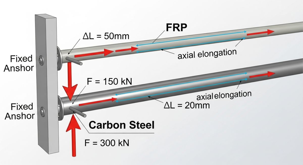
FRP vs Carbon Steel Thermal Expansion and Anchor Load Differences
In my 20+ years of designing industrial piping systems, I have seen many engineers make the catastrophic mistake of treating Fiber Reinforced Plastic (FRP) exactly like carbon steel. While FRP offers unmatched corrosion resistance in aggressive chemical and water services, its physical response to temperature changes is fundamentally different. If you design an FRP system using carbon steel support rules, you will either buckle the pipe or over-design your structural anchors to a ridiculous degree.
I wrote this guide to break down the exact physics, math, and code requirements governing thermal elongation and anchor loads for both materials. By understanding how the low elastic modulus of FRP offsets its high thermal expansion rate, you can optimize your pipe racks, reduce structural steel costs, and guarantee long-term system integrity.
Key Engineering Takeaways
- FRP expands axially up to two to four times more than carbon steel under the same temperature differential.
- Despite higher expansion, FRP generates up to ten times lower anchor loads due to its significantly lower tensile modulus.
- FRP is highly susceptible to structural buckling, requiring much closer guide spacing than carbon steel.
- Anisotropic properties of FRP mean thermal expansion varies based on the glass filament winding angle.
Complete Course on
Piping Engineering
Check Now
Key Features
- 125+ Hours Content
- 500+ Recorded Lectures
- 20+ Years Exp.
- Lifetime Access
Coverage
- Codes & Standards
- Layouts & Design
- Material Eng.
- Stress Analysis
Analyzing FRP vs Carbon Steel Thermal Expansion in Piping Systems
To understand the differences, we must look at the material structures. Carbon steel is an isotropic material; its physical properties are identical in all directions. FRP, however, is an anisotropic composite. Its mechanical properties depend heavily on the glass-to-resin ratio and, more importantly, the winding angle of the glass fibers.
For a typical filament-wound FRP pipe with a winding angle of 55 degrees, the axial coefficient of thermal expansion is significantly higher than that of carbon steel. Let us look at the fundamental equations governing thermal elongation and anchor loads.
The Governing Equations
The thermal elongation of an unrestrained pipe run is calculated using the following formula:
Where:
- dL = Thermal elongation (mm)
- L = Length of the pipe run (mm)
- alpha = Coefficient of thermal expansion (mm/mm/°C)
- dT = Temperature difference between operating and installation temperature (°C)
When a pipe is fully restrained between two rigid anchors, the thermal strain is converted into axial stress. The resulting compressive anchor force is calculated as:
Where:
- F = Thermal anchor force (N)
- A = Cross-sectional area of the pipe wall (mm²)
- E = Modulus of elasticity of the pipe material (MPa)
The Modulus of Elasticity Paradox
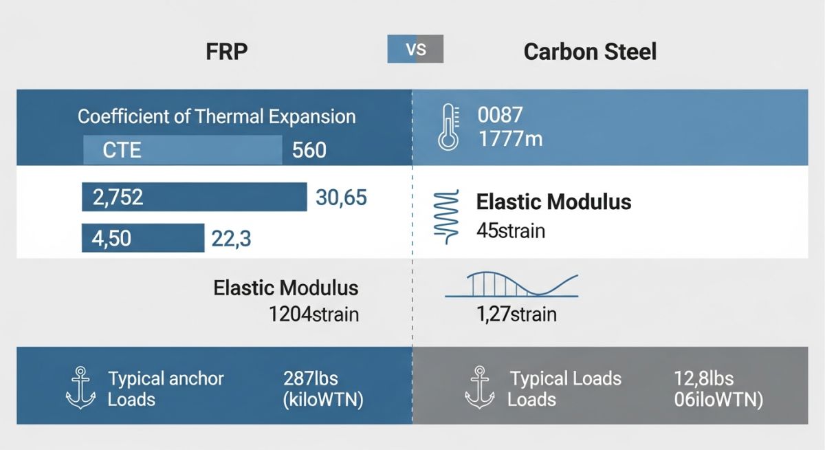
This is where the engineering gets interesting. While the thermal expansion coefficient (alpha) of FRP is roughly 1.5 to 2.5 times higher than carbon steel, its axial modulus of elasticity (E) is 15 to 20 times lower.
Because the anchor force is directly proportional to the product of the modulus of elasticity and the thermal expansion coefficient (E * alpha), the resulting anchor load for an FRP system is dramatically lower than that of an equivalent carbon steel system.
When designing these systems under ASME B31.3 Chapter VII, you must perform a formal flexibility analysis if the system operating temperature exceeds 60°C. For carbon steel, standard loop designs work beautifully. For FRP, you must carefully balance the use of expansion loops, directional changes, and structural guides to control the low-stiffness pipe.
The table below compares the physical and thermal properties of typical filament-wound Epoxy/Glass FRP (55-degree winding angle) against standard ASTM A106 Grade B Carbon Steel. These values are critical for inputting accurate data into stress analysis software like CAESAR II.
| Property | Carbon Steel (ASTM A106 Gr. B) | FRP (Epoxy/Glass 55° Wind) | Ratio (FRP to CS) |
|---|---|---|---|
| Density (kg/m³) | 7,850 | 1,800 | 0.23 (77% Lighter) |
| Thermal Expansion Coeff. (mm/m/°C) | 0.0117 | 0.0200 (Axial) | 1.71 times higher |
| Modulus of Elasticity (GPa) | 200 | 12.5 (Axial) | 0.06 (16 times lower) |
| Thermal Conductivity (W/m·K) | 54 | 0.35 | 0.006 (Excellent Insulator) |
| Typical Support Span (m) (DN 150 / 6″) | 5.2 | 3.1 | 0.60 (Requires closer support) |
This matrix maps the core design standards, structural parameters, and compliance pathways for both piping materials under thermal loading conditions.
| Design Parameter | Carbon Steel Piping | FRP Piping Systems | Applicable Standards |
|---|---|---|---|
| Primary Design Code | ASME B31.3 Chapter II | ASME B31.3 Chapter VII | ASME B31.3 |
| Composite Standard | Not Applicable | ISO 14692 / AWWA C950 | ISO 14692 |
| Stress Limits | Allowable Stress (S) based on Yield/Tensile | Long-term Hydrostatic Strength (LTHS) with design factors | ASTM D2992 / ISO 14692 |
| Thermal Analysis Method | Beam bending theory, isotropic expansion | Anisotropic shell/beam theory, orthotropic properties | CAESAR II / AutoPIPE |
| Anchor Design Focus | High load capacity, structural steel reinforcement | Low load capacity, localized shear web stress on pipe wall | FRP Manufacturer Guidelines |
Mitigating FRP vs Carbon Steel Thermal Expansion Risks in Design
When transitioning a piping design from carbon steel to FRP, or when managing a mixed-material facility, you must follow a strict verification protocol. I have developed this checklist over years of troubleshooting field failures to ensure your engineering team does not miss critical design steps.
Engineering Design & Field Verification Checklist
-
Verify Material Properties in Stress Software: Ensure that the orthotropic properties of the specific FRP manufacturer (axial/hoop modulus, Poisson’s ratios, and axial thermal expansion) are input correctly into CAESAR II. Do not use generic database values.
-
Calculate Critical Buckling Spacing: Verify that guide spacing for FRP lines is calculated using the Euler buckling formula modified for low-modulus composite materials. Guide spacing must be significantly tighter than carbon steel.
-
Check Guide Clearances: Ensure that pipe guides on FRP lines have adequate radial clearance (typically 2mm to 3mm) to prevent binding and localized wear on the composite pipe outer diameter.
-
Validate Anchor Localized Shear Stress: Ensure that anchors on FRP lines distribute the load over a wide area using laminated saddles or heavy-duty wear pads. Point-loading an FRP pipe wall will cause immediate structural shear failure.
-
Review Expansion Joint Requirements: If using bellows or slip-type expansion joints, verify that the activation force of the joint does not exceed the structural buckling limit of the adjacent FRP pipe run.
Field Case Study: Real-World Application
The Problem: Catastrophic Buckling of a Cooling Water Header
At a chemical processing facility in Gujarat, India, a 400-meter-long, DN 250 (10-inch) carbon steel cooling water header was replaced with Glass-Reinforced Epoxy (GRE) FRP to eliminate severe internal corrosion. The field construction team kept the original carbon steel support and guide spacing of 6.2 meters.
During summer commissioning, when the water temperature rose from the 25°C installation temperature to the 50°C operating temperature, the GRE line suffered severe lateral snaking and structural buckling between the guides. The excessive lateral movement caused several adhesive-bonded joints to crack, resulting in a complete plant shutdown.
The Outcome: Redesign and Structural Remediation
I was brought in to analyze the failure. Using ISO 14692 guidelines, we calculated that the critical buckling load of the GRE pipe was exceeded by 180% due to the wide 6.2-meter guide spacing.
We immediately redesigned the support system by reducing the guide spacing to 2.8 meters. We also verified that the existing concrete structural anchors were more than adequate. Because the GRE pipe has a low modulus of elasticity, the actual thermal anchor load dropped from the original carbon steel design value of 145 kN down to a mere 18 kN.
By adding intermediate guides and utilizing the existing anchors without any structural reinforcement, we stabilized the line. The system has now been operating flawlessly for over five years without a single leak or structural deflection.
My direct recommendation from this project is clear: when replacing carbon steel with FRP, always recalculate the guide spacing for buckling resistance. Do not assume that because the anchor loads are lower, the system is safer.
Frequently Asked Engineering Questions
Why does FRP generate lower anchor loads than carbon steel despite expanding more?
How does the filament winding angle affect FRP thermal expansion?
What are the primary design codes for analyzing FRP thermal stress?
Can we use standard carbon steel expansion joints in FRP piping systems?
How do guide spacing requirements differ between FRP and carbon steel?
What is the impact of temperature on the mechanical properties of FRP vs carbon steel?
===
