What is Burst Testing? Burst Testing vs Hydrostatic Testing Guide
In my 20 years of managing piping systems and pressure vessel integrity, I have stood in high-pressure testing bays where the difference between a controlled test and a catastrophic failure was measured in fractions of a millimeter. I remember a project in 2018 where a client insisted on substituting a standard hydrostatic test with a burst test on production-run piping. It took a detailed technical intervention to explain that doing so would completely destroy their expensive, custom-fabricated manifold.
Understanding how these two pressure testing methodologies differ is not just an academic exercise. It is a fundamental safety and quality control requirement. While one method is designed to verify that a system can safely operate under design loads without leaking, the other is designed to push the material past its physical limits until it violently ruptures. Let us break down the mechanics, calculations, and field realities of these two indispensable testing protocols.
Key Engineering Takeaways
- Destructive vs. Non-Destructive: Burst testing destroys the test specimen to find its ultimate limit, whereas hydrostatic testing preserves the component for field service.
- Pressure Ratios: Hydrostatic tests typically operate at 1.3 to 1.5 times the Maximum Allowable Working Pressure (MAWP), while burst tests often exceed 4 to 10 times the design pressure.
- Code Compliance: Hydrostatic testing is a mandatory field validation under ASME B31.3 and ASME Section VIII, while burst testing is primarily used for R&D, batch validation, and component rating.
Complete Course on
Piping Engineering
Check Now
Key Features
- 125+ Hours Content
- 500+ Recorded Lectures
- 20+ Years Exp.
- Lifetime Access
Coverage
- Codes & Standards
- Layouts & Design
- Material Eng.
- Stress Analysis
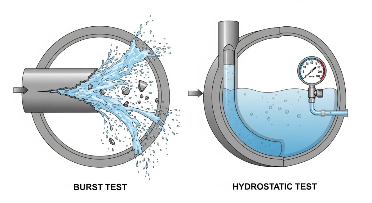
Understanding Burst Testing vs Hydrostatic Testing Differences
To grasp the core differences, we must look at the physical state of the material during testing. During a hydrostatic test, the stress induced in the pipe wall or vessel shell must remain well within the elastic region of the material’s stress-strain curve. We are verifying that the system behaves elastically and returns to its original dimensions once the pressure is vented.
Conversely, burst testing deliberately forces the material through its elastic limit, past its yield point, and deep into the plastic deformation zone until it reaches its ultimate tensile strength (UTS) and ruptures. This destructive test is critical for establishing the actual safety factor of a design.
Never attempt a burst test in an open field or without a certified blast containment chamber. The stored energy in a component pressurized to its rupture point can release shrapnel with lethal velocity, even when using relatively incompressible fluids like water.
The Mathematics of Pressure Containment
To calculate the theoretical pressures required for both tests, we rely on Barlow’s Formula for hoop stress. Hoop stress is the circumferential stress acting on the pipe wall due to internal pressure:
Barlow’s Formula:
P = (2 * S * t) / D
Where:
- P = Internal pressure (psi or MPa)
- S = Allowable stress, yield strength, or tensile strength (psi or MPa)
- t = Nominal wall thickness of the pipe (inches or mm)
- D = Outside diameter of the pipe (inches or mm)
Practical Engineering Calculation Example
Let us calculate both the hydrostatic test pressure and the theoretical burst pressure for an ASTM A106 Grade B seamless carbon steel pipe.
- Outside Diameter (D): 4.500 inches (114.3 mm) – NPS 4 Schedule 40
- Wall Thickness (t): 0.237 inches (6.02 mm)
- Specified Minimum Yield Strength (SMYS): 35,000 psi (240 MPa)
- Specified Minimum Tensile Strength (SMTS): 60,000 psi (415 MPa)
- Allowable Stress (S) at ambient temperature: 20,000 psi (138 MPa) per ASME B31.3
Step 1: Calculate the Hydrostatic Test Pressure (ASME B31.3 Standard)
Typically, the hydrostatic test pressure is 1.5 times the design pressure. If our system design pressure is limited by the pipe’s allowable stress at 100% efficiency:
Design Pressure (P_design) = (2 * S * t) / D = (2 * 20,000 * 0.237) / 4.500 = 2,106 psi (14.52 MPa)
Hydrostatic Test Pressure (P_hydro) = 1.5 * P_design = 1.5 * 2,106 = 3,159 psi (21.78 MPa)
At this hydrostatic pressure, the stress in the pipe wall is:
S_hydro = (P_hydro * D) / (2 * t) = (3,159 * 4.500) / (2 * 0.237) = 30,000 psi
Note that 30,000 psi is safely below the material’s yield strength of 35,000 psi. The pipe remains completely in its elastic range.
Step 2: Calculate the Theoretical Burst Pressure
To find the pressure at which the pipe will physically rupture, we substitute the Tensile Strength (SMTS) into Barlow’s Formula:
P_burst = (2 * SMTS * t) / D = (2 * 60,000 * 0.237) / 4.500 = 6,320 psi (43.57 MPa)
This calculation demonstrates that the burst pressure (6,320 psi) is more than double the hydrostatic test pressure (3,159 psi). This gap represents the structural safety margin designed to prevent catastrophic failures during unexpected system overpressurization.
Technical Parameters of Burst Testing vs Hydrostatic Testing
In my field experience, selecting the correct test protocol depends heavily on the stage of the project. R&D and manufacturing quality control rely on burst testing to validate design assumptions. Field construction and plant maintenance rely exclusively on hydrostatic testing to verify system integrity before commissioning.
| Technical Parameter | Burst Testing | Hydrostatic Testing |
|---|---|---|
| Primary Objective | Determine ultimate failure limit and rupture behavior. | Verify leak-tightness and structural integrity. |
| Test Classification | Destructive Testing (DT) | Non-Destructive Testing (NDT) |
| Typical Test Pressure | Calculated burst limit (often 4x to 10x MAWP) | 1.3x to 1.5x Maximum Allowable Working Pressure |
| Material State | Plastic deformation and physical rupture | Strictly within the elastic range |
| Component Reusability | No (Specimen is permanently destroyed) | Yes (Component is placed into service) |
| Governing Codes | ASTM D1599, ISO 1167, ASME Section VIII Div 1 (Proof Test) | ASME B31.3, ASME Section VIII, API 510 |
To ensure precise communication across engineering teams, we must map the core technical entities, structural acronyms, and physical parameters to their respective industry standards.
| Entity / Acronym | Technical Definition | Physical Parameter | Standard Reference |
|---|---|---|---|
| MAWP | Maximum Allowable Working Pressure at design temperature. | Pressure (psi / bar) | ASME Section VIII Div 1 |
| SMYS | Specified Minimum Yield Strength of the material. | Stress (psi / MPa) | ASTM A106 / API 5L |
| SMTS | Specified Minimum Tensile Strength where rupture occurs. | Stress (psi / MPa) | ASTM A370 |
| Hoop Stress | Circumferential stress acting perpendicular to the longitudinal axis. | Stress (psi / MPa) | Barlow’s Equation |
Field Verification Checklist for Pressure Testing
Before executing any pressure test on-site, I walk the line with this checklist. Skipping even a single step can lead to catastrophic failure, equipment damage, or severe injury.
Pre-Test Field Verification Steps
-
Verify Gauge Calibration: Ensure all pressure gauges have been calibrated within the last 6 months and have valid calibration tags. -
Isolate Low-Pressure Equipment: Confirm that control valves, transmitters, and low-pressure instruments are physically isolated or removed from the test loop. -
Install High-Point Vents: Ensure high-point vents are open during filling to completely purge air from the system before pressurization. -
Check Temp Stabilization: Allow the test medium (water) to reach thermal equilibrium with the pipe wall to prevent pressure fluctuations. -
Establish Exclusion Zone: Erect physical barriers and warning signs around the test area to keep non-essential personnel at a safe distance. -
Verify Relief Valve Setting: Confirm that a calibrated pressure relief valve is installed on the test pump, set at 10% above the target test pressure. -
Inspect Temporary Supports: Verify that temporary structural supports are installed to handle the added weight of the water medium in gas lines.
Field Case Study: Real-World Application
The Problem: Premature Manifold Failure
During the commissioning of a high-pressure water injection manifold rated for 5,000 psi, a standard hydrostatic test was conducted at 7,500 psi (1.5x design pressure). Within 12 minutes of holding the pressure, a major weld joint cracked, causing a rapid loss of pressure. The contractor claimed the design was faulty, while the fabricator insisted the welding met all specifications.
The Investigation & Outcome
I was brought in to perform a root cause analysis. We cut out the failed weld joint and sent it to a metallurgical lab. To resolve the dispute, we performed a destructive burst test on an identical, sacrificial manifold section fabricated under the same conditions.
The burst test revealed that the sacrificial section ruptured at only 9,200 psi, far below the theoretical burst pressure of 15,000 psi. Microscopic analysis showed severe hydrogen embrittlement and micro-cracking in the Heat Affected Zone (HAZ) due to inadequate pre-heating during welding.
By using burst testing on a sample, we proved that the fabrication process was flawed without destroying the remaining field components. The fabricator re-welded the entire manifold using correct pre-heating procedures, and the subsequent hydrostatic test was passed successfully.
Frequently Asked Engineering Questions
Can a hydrostatic test replace a burst test?
Why is water preferred over air for hydrostatic testing?
What is the standard safety margin for a burst test?
How does temperature affect the results of these tests?
What is a “proof test” under ASME Section VIII?
How do you handle a pressure drop during a hydrostatic test?
===

📚 Recommended Resources: burst testing vs hydrostatic testing
Read these Guides
🎥 Watch Tutorials

Related posts:
![Cross-section diagram showing a steel solar pile foundation embedded in layered soil profiles for structural analysis.]()
Essential Geotechnical Pile Design Data for Utility-Scale Solar Structures
![Professional surveyor conducting Topographical Surveys for Solar Projects on a large-scale utility site with complex terrain.]()
Topographical Surveys for Solar Projects: A Technical Engineering Guide
![A geotechnical drill rig performing soil sampling on a large, open field intended for a utility-scale solar farm project.]()
Geotechnical Investigation for Solar Farms: Essential Site Design Guide
![Isometric site plan showing Utility Corridor Planning for Data Centres with color-coded power, water, and telecom infrastructure paths.]()
Utility Corridor Planning for Data Centres: A Strategic Engineering Guide
![Aerial view of a data centre site showcasing perimeter drainage systems, detention basins, and site grading for flood prevention.]()
Drainage Design Considerations for Data Centres: A Technical Guide
![Professional surveyor using a Total Station on a large data centre construction site for topographical mapping.]()
Topographical Surveys for Data Centre Projects: A Technical Guide