Table of Contents
Understanding the Different Types of Pipe Threads in Piping Systems
In my 20 years of piping engineering, I have seen minor thread mismatches lead to catastrophic plant shutdowns. A field technician looks at a threaded fitting, assumes it fits because it spins hand-tight for two turns, and applies system pressure. Within minutes, the joint fails, spraying hazardous chemicals across the skid. Identifying the correct types of pipe threads is not just a drafting exercise; it is a fundamental safety requirement for pressure piping systems.
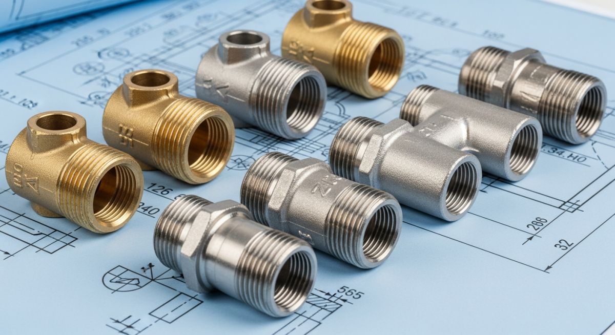
Whether you are working with National Pipe Taper (NPT), British Standard Pipe (BSP), Metric, or Unified threads, each profile has unique sealing mechanics, thread angles, and pitch configurations. Mixing these standards without proper adapters destroys the thread flanks, compromises joint integrity, and introduces severe leak paths.
- Never force-fit mismatched thread profiles; even a slight pitch variation will gall the metal and cause joint failure.
- Tapered threads seal via metal-to-metal contact and require thread sealant, whereas parallel threads rely on gaskets or O-rings.
- Always verify thread pitch and diameter using calibrated pitch gauges and calipers before final installation.
Complete Course on
Piping Engineering
Check Now
Key Features
- 125+ Hours Content
- 500+ Recorded Lectures
- 20+ Years Exp.
- Lifetime Access
Coverage
- Codes & Standards
- Layouts & Design
- Material Eng.
- Stress Analysis
Demystifying the Primary Types of Pipe Threads
Industrial Thread Profiles: Geometric configurations of crests, roots, and flanks engineered to establish mechanical holding power and pressure-tight seals. These profiles dictate whether a joint relies on thread deformation or an auxiliary elastomeric gasket to contain pressurized fluids.
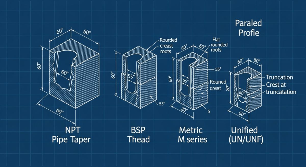
To select the correct fitting, we must analyze the geometry of the four primary thread families used in global piping networks.
1. National Pipe Taper (NPT)
Governed by the ASME B1.20.1 standard, NPT is the dominant thread type in North American industrial piping. It features a 60-degree thread angle and a 1-in-16 taper (3/4 inch per foot) along the pipe axis. The taper allows the male and female threads to wedge together, flattening the crests and roots to form a metal-to-metal seal. However, a spiral leak path remains along the thread tips, requiring the application of PTFE tape or a liquid thread sealant.
2. British Standard Pipe (BSP)
Widely adopted across Europe, Asia, and the Commonwealth, BSP threads utilize the Whitworth 55-degree thread angle with rounded crests and roots. BSP is split into two critical sub-types:
- BSPT (Tapered): Governed by ISO 7, BSPT functions similarly to NPT, sealing via thread wedging.
- BSPP (Parallel): Governed by ISO 228, BSPP threads do not taper. They serve purely as a mechanical fastener, relying on a bonded washer (Dowty seal), O-ring, or flat gasket to contain pressure.
3. Metric Threads (M-Series)
Commonly found on European hydraulic systems and machinery, Metric threads are parallel threads defined by ISO 261. They feature a 60-degree thread angle. Because they are parallel, they require an elastomeric seal, such as an O-ring at the thread shoulder or a cutting ring, to prevent fluid bypass.
4. Unified Threads (UNC/UNF)
Defined by ASME B1.1, Unified National Coarse (UNC) and Unified National Fine (UNF) threads are parallel fastening threads. While not designed for direct pipe-to-pipe fluid sealing, they are extensively used in hydraulic port connections (such as SAE straight thread O-ring boss joints) where an O-ring provides the fluid barrier.
A 1/2″ NPT male thread and a 1/2″ BSPT male thread both have 14 threads per inch (TPI) and highly similar diameters. However, the NPT thread has a 60° angle, while the BSPT has a 55° angle. If you force them together, they will bind after a few turns, creating a false sense of security. Under pressure, this mismatched joint will leak or blow out entirely. Always verify the thread standard before assembly.
Engineering Calculations: Thread Shear and Blowout Force
To ensure a threaded joint can withstand system design pressure, we must calculate the axial blowout force and compare it to the shear strength of the engaged threads.
The axial blowout force (F_b) acting on the joint is calculated as:
Where:
P = Design pressure of the system (psi or MPa)
A_p = Internal cross-sectional area of the pipe based on the outer diameter of the thread (A_p = pi * D^2 / 4)
The thread shear area (A_s) for the female thread is calculated using:
Where:
n = Threads per inch (TPI)
L_e = Length of thread engagement (inches)
D_min = Minimum minor diameter of the female thread
d_2 = Basic pitch diameter of the male thread
D_max = Maximum major diameter of the female thread
The safety factor (SF) against thread shear is then determined by:
Where S_s is the allowable shear stress of the fitting material (typically taken as 60% of the material’s yield strength, S_y). For high-pressure systems, a minimum safety factor of 4.0 is standard practice.
Dimensional Specifications for Common Pipe Threads
Thread Dimension Standards: Standardized geometric parameters defining pitch, major diameter, and threads per inch to ensure global interchangeability. These values govern the machining tolerances and inspection criteria for high-pressure piping components.
| Nominal Size (Inches) | NPT Pitch (TPI) | NPT Major Dia. (in) | BSP Pitch (TPI) | BSP Major Dia. (mm) | Metric Equivalent |
|---|---|---|---|---|---|
| 1/8″ | 27 | 0.405 | 28 | 9.73 | M10 x 1.0 |
| 1/4″ | 18 | 0.540 | 19 | 13.16 | M14 x 1.5 |
| 3/8″ | 18 | 0.675 | 19 | 16.66 | M16 x 1.5 |
| 1/2″ | 14 | 0.840 | 14 | 20.96 | M20 x 1.5 |
| 3/4″ | 14 | 1.050 | 14 | 26.44 | M26 x 1.5 |
| 1″ | 11.5 | 1.315 | 11 | 33.25 | M33 x 2.0 |
| Thread Type | Standard Reference | Sealing Mechanism | Common Application | Pressure Rating Class |
|---|---|---|---|---|
| NPT | ASME B1.20.1 | Metal-to-metal with sealant | Process piping, oil & gas | Up to 10,000 PSI (Class 3000/6000) |
| BSPT | ISO 7-1 / BS 21 | Metal-to-metal with sealant | Water systems, utility lines | Medium pressure utility |
| BSPP | ISO 228-1 | O-ring, bonded washer, or gasket | Hydraulics, pneumatic systems | High pressure hydraulic |
| Metric | ISO 261 / ISO 965 | O-ring or cutting ring | European machinery, automotive | High pressure hydraulic |
| Unified (UNF) | ASME B1.1 | O-ring boss (ORB) | Fluid power, aerospace | High pressure fluid power |
Field Verification Checklist for Pipe Threads
Thread Inspection Protocol: Quality control procedures executed at the job site to verify thread integrity, profile match, and sealant application prior to system pressurization. This checklist prevents catastrophic joint blowouts and fugitive emissions during commissioning.
Before assembling any threaded connection in a process plant, the field inspector or piping supervisor must execute the following verification steps:
-
Visual Profile Inspection: Check for damaged, flattened, or galled thread crests. Reject any fittings showing visible nicks or corrosion.
-
Pitch Gauge Verification: Use a calibrated thread pitch gauge to confirm the exact threads per inch (TPI) or metric pitch. Do not rely on visual estimation.
-
Taper vs. Parallel Check: Confirm if the female port is parallel or tapered. Remember that a tapered male thread (NPT) should never be mated to a parallel female port (BSPP) unless specifically designed with an adapter.
-
Sealant Compatibility: Verify that the thread sealant (PTFE tape or anaerobic compound) is chemically compatible with the process fluid (e.g., oxygen service requires specialized oil-free sealant).
-
Torque and Engagement: Ensure the joint is tightened to the specified hand-tight plus turns (T.G.P. – Thread Engagement Practice) or torque value to prevent over-stressing the female fitting.
Field Case Study: Real-World Application
During commissioning of a high-pressure hydraulic lubrication skid at a combined-cycle power plant, the field team reported persistent weeping at the main pump discharge manifold. The design drawing specified a 3/4″ BSPP port. However, during a rushed maintenance shift, a technician had forced a 3/4″ NPT male adapter into the port. Because the threads bound tightly after three turns, the technician assumed the joint was secure and applied heavy system pressure (3,200 PSI). Within hours, the joint began leaking, spraying synthetic oil and creating a severe fire hazard.
I was called to the site to troubleshoot. Upon disassembly, we found severe thread galling on the female manifold block. The 60-degree NPT male thread had cross-threaded and deformed the 55-degree BSPP female thread. We re-machined the manifold port to clean the threads, verified the dimensions using a thread go/no-go gauge, and installed a proper 3/4″ BSPP male to 3/4″ NPT female adapter. The BSPP side utilized a Viton bonded sealing washer to establish a positive seal against the flat face of the manifold. The system was pressure tested to 4,800 PSI (1.5 times design pressure) and held perfectly with zero leakage.
This incident highlights why field personnel must be trained to identify different types of pipe threads. Relying on “feel” or forcing fittings with a pipe wrench is a recipe for mechanical failure and costly downtime.
Frequently Asked Engineering Questions
Can I mix NPT and BSPT threads in a high-pressure system?
What is the difference between BSPP and BSPT?
How do I identify an unknown pipe thread in the field?
Why do parallel threads require a gasket or O-ring to seal?
What is the purpose of dryseal threads (NPTF)?
How does temperature affect the selection of thread sealants?

📚 Recommended Resources: types of pipe threads
Read these Guides


Related posts:
![Industrial metallic piping network with stainless steel pipes and valves in a processing plant.]()
What is Metallic Piping: Types, Advantages, Applications, and ASTM Standards
![Industrial gas processing facility comparing cryogenic LNG storage tanks and pressurized LPG bullet tanks.]()
What are the Differences Between LNG and LPG?
![Split-screen comparison of liquid oil failing under extreme heat versus dry graphite lubricating a mechanical bearing smoothly.]()
Why Is Graphite a Better Lubricant Than Oil in Industrial Piping?
![Tall industrial distillation column tower at a chemical processing plant]()
What is a Distillation Column? Working Principles and Types
![A collection of different metal and plastic pipe ferrules resting on an engineering blueprint.]()
How Do Pipe Ferrules Ensure Leak-Free Industrial Piping Systems?
![Close-up of heavy-duty industrial piping fasteners securing a steel flange joint.]()
Piping Fasteners: Engineering Selection, Torque Calculations, and Installation Standards