What is Power Piping? Power Piping vs Process Piping Explained
When I walk onto a combined-cycle power plant or a petrochemical refinery, the first thing I look at is the piping specification. Over the past two decades, I have seen millions of dollars wasted and catastrophic failures occur simply because a design team failed to grasp the fundamental differences between power piping and process piping. These are not just different chapters in a handbook; they represent entirely different engineering philosophies, safety margins, and legal jurisdictions.
In my experience, misapplying these codes is one of the most common errors made by multi-disciplinary engineering firms. Power piping systems operate under extreme thermal cycles and high pressures, demanding conservative safety factors. Process piping, on the other hand, must handle an incredibly diverse range of fluids—from highly toxic chemicals to simple utility water—requiring complex fluid categorization and material compatibility assessments.
Key Engineering Takeaways
- ASME B31.1 Jurisdiction: Applies to high-pressure steam boilers and power generation systems, with strict legal boundaries for Boiler External Piping (BEP).
- ASME B31.3 Flexibility: Covers chemical, refinery, and pharmaceutical plants, offering tailored design rules based on fluid hazard categories.
- Wall Thickness Differences: Power piping generally requires thicker walls due to more conservative allowable stress safety factors.
- Inspection Rigor: Process piping inspection levels scale with fluid toxicity, whereas power piping inspections focus heavily on high-temperature creep and thermal fatigue.
Complete Course on
Piping Engineering
Check Now
Key Features
- 125+ Hours Content
- 500+ Recorded Lectures
- 20+ Years Exp.
- Lifetime Access
Coverage
- Codes & Standards
- Layouts & Design
- Material Eng.
- Stress Analysis
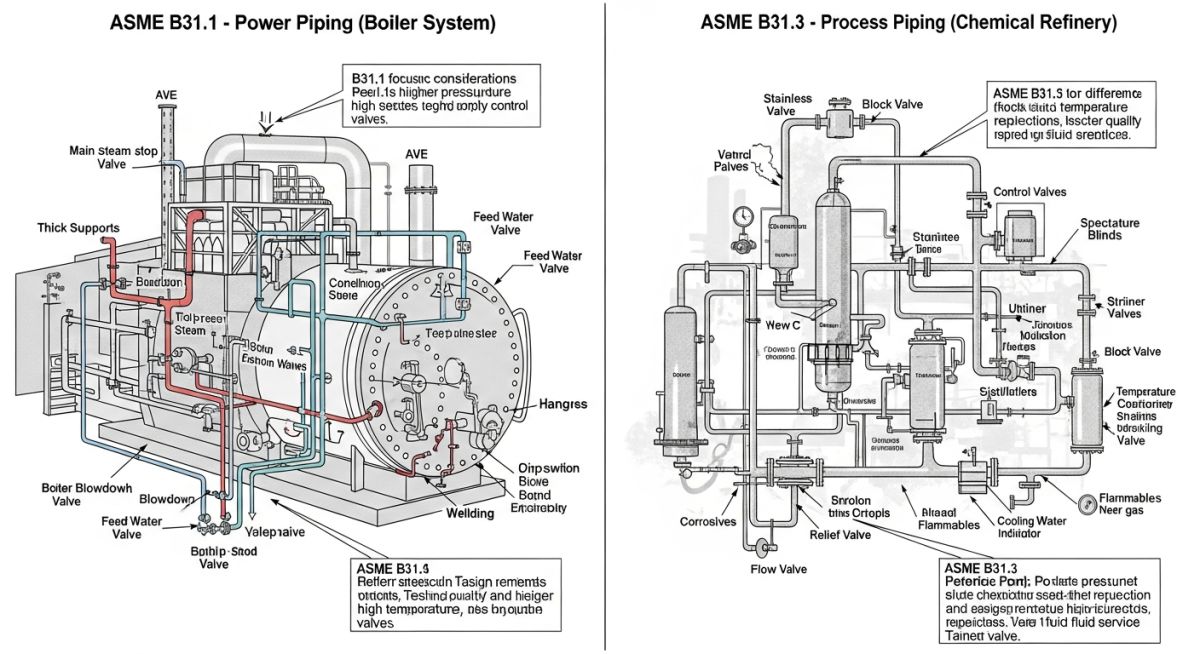
Understanding Power Piping vs Process Piping Codes
To understand the core differences, we must look at the governing standards. Power piping is designed under the ASME B31.1 Power Piping Code. This code specifically targets systems found in electric generating stations, industrial steam plants, and high-temperature water systems. The primary focus here is thermodynamic efficiency, high-temperature creep, and extreme thermal expansion.
Conversely, process piping falls under the ASME B31.3 Process Piping Code. This standard is designed to handle the vast complexities of chemical plants, petroleum refineries, and pharmaceutical facilities. Because these plants process thousands of different chemicals, B31.3 introduces fluid service categories (such as Category D, Category M, High Pressure, and Normal Fluid Service) to match the design rigor with the hazard level of the fluid.
Wall Thickness Calculations and Safety Factors
The mathematical approach to wall thickness highlights the conservative nature of power piping. Under ASME B31.1, the minimum required wall thickness ™ is calculated using the following formula:
Where:
• P = Internal design pressure (psig)
• D = Outside diameter of the pipe (inches)
• S = Allowable stress value for the material at design temperature (psi)
• E = Weld joint efficiency factor
• Y = Coefficient representing material plasticity at high temperatures
• A = Additional thickness to compensate for corrosion, erosion, or mechanical threading (inches)
For process piping under ASME B31.3, the basic wall thickness formula is similar, but it incorporates a weld joint strength reduction factor (W) for elevated temperatures:
The critical difference lies in the allowable stress (S). ASME B31.1 uses a more conservative safety factor (typically 3.5 or 4.0 based on tensile strength depending on the specific material and temperature limits), whereas ASME B31.3 uses a safety factor of 3.0. This means that for the exact same pressure, temperature, and material, a B31.1 power pipe will almost always have a thicker wall than a B31.3 process pipe.
I have witnessed several projects face severe regulatory delays because the design team classified Boiler External Piping (BEP) as B31.3 or non-boiler external piping. BEP is the piping that connects the boiler to the first valve. It is strictly governed by ASME Section I and ASME B31.1. It requires an Authorized Inspector (AI) to review the design, witness the hydrostatic test, and sign off on the ASME data forms. Misclassifying this boundary is a major compliance violation that can force you to cut out and replace completed welds.
Key Differences in Power Piping vs Process Piping
Another major point of divergence is how each code handles fluid hazards. ASME B31.1 assumes the fluid is almost always steam or water. Because these fluids are predictable, the code does not require the designer to categorize the fluid. The focus is purely on managing high temperatures and pressures.
In contrast, ASME B31.3 deals with highly volatile, toxic, and flammable substances. The designer must classify the fluid service into one of several categories. For example, Category M fluid service is reserved for highly toxic fluids where a single leak can cause immediate, irreversible harm to personnel. This classification triggers extremely stringent design, fabrication, and non-destructive examination (NDE) requirements, such as 100% radiography of all circumferential butt welds.
To help clarify these distinctions for your engineering team, I have compiled two comprehensive reference tables. The first table compares the core design parameters of both codes, while the second maps specific industrial systems to their correct code jurisdictions.
| Design Parameter | ASME B31.1 (Power Piping) | ASME B31.3 (Process Piping) |
|---|---|---|
| Primary Application | Power stations, high-pressure steam boilers, central heating plants. | Refineries, chemical plants, pharmaceutical, paper, and textile mills. |
| Safety Factor (Tensile) | More conservative (typically 3.5 to 4.0 depending on material). | Less conservative (typically 3.0, allowing thinner walls). |
| Fluid Categorization | None. Assumes steam, water, or non-flammable utility fluids. | Extensive (Category D, Category M, Normal, High Pressure, High Purity). |
| Weld Joint Factors | Strictly defined based on weld type and NDE performed. | Includes weld joint strength reduction factors (W) for high temperatures. |
| Hydrostatic Test Pressure | 1.5 times the design pressure. | 1.5 times the design pressure multiplied by the temperature ratio. |
| System Component | Applicable Code | Material Specification | NDT Requirement | Stress Analysis Focus |
|---|---|---|---|---|
| Main Steam Line (600 psi, 850°F) | ASME B31.1 | ASTM A335 Gr. P11 / P22 | 100% Radiography (RT) & Magnetic Particle (MT) | High-temperature creep, thermal expansion, spring hanger design. |
| Hydrocarbon Process Line | ASME B31.3 | ASTM A106 Gr. B / A312 TP316 | Random Visual (VT) & 10% RT (Normal Fluid) | Flange leakage, nozzle loads on pumps, chemical corrosion. |
| Boiler Feedwater Line | ASME B31.1 | ASTM A106 Gr. C | Visual & Ultrasonic Testing (UT) | Water hammer, transient hydraulic loads, erosion-corrosion. |
| Toxic Chemical Line (Category M) | ASME B31.3 | ASTM A312 TP316L | 100% Radiography (RT) & Bubble Leak Test | Zero-leakage joints, bellows expansion joints, valve packing. |
Site Verification for Power Piping Systems
Before any piping system is pressurized, a rigorous field verification process must occur. In my years of managing site installations, I have found that a structured checklist is the best defense against costly field reworks and safety hazards. Use this checklist during your next pre-commissioning walkdown.
Pre-Commissioning Walkdown Checklist
-
Code Boundary Verification: Confirm that the physical transition from ASME Section I (Boiler External Piping) to ASME B31.1 (Non-Boiler External Piping) matches the approved P&IDs exactly.
-
Material Traceability (MTRs): Verify that all high-alloy piping materials (such as P11, P22, or P91) have matching Material Test Reports and have undergone positive material identification (PMI) testing.
-
Spring Hanger Travel Stops: Ensure all spring hangers have their travel stops removed *after* hydrostatic testing but *before* thermal hot-commissioning.
-
NDE Clearance: Confirm that all required radiographic, ultrasonic, and magnetic particle examinations are complete, documented, and signed off by a certified Level II/III inspector.
-
Hydrostatic Test Venting: Verify that high-point vents are open during system filling to prevent air pockets, and that the test pressure is held for the minimum duration specified by the governing code.
Field Case Study: Real-World Application
During a routine shutdown inspection at a 450MW combined cycle power plant, inspectors discovered severe cracking at the weld joints of a 12-inch high-pressure steam line. The line operated at 650 psi and 850°F. Upon reviewing the original design documentation, I discovered that the EPC contractor had designed this steam line using the ASME B31.3 (Process Piping) code instead of ASME B31.1 (Power Piping). The contractor had utilized the less conservative safety factor of B31.3 to reduce the pipe wall thickness, saving material costs. However, the thinner pipe walls could not withstand the severe thermal cycling and transient water hammer events during startup, leading to rapid fatigue cracking.
I immediately ordered the suspension of operations on that steam header. We re-engineered the entire system to comply with ASME B31.1. This required increasing the pipe wall thickness from Schedule 40 to Schedule 80, replacing the standard carbon steel with ASTM A335 Grade P22 alloy steel, and redesigning the spring hangers to accommodate the increased weight and thermal expansion. We also performed 100% radiography on all new welds. While the remediation cost the owner 450,000 in materials and labor, it prevented a catastrophic steam rupture that could have resulted in severe injuries and millions of dollars in property damage. The system has now operated safely for over eight years.
This case study highlights why code compliance is not optional. Saving a few thousand dollars on thinner pipe walls by misapplying ASME B31.3 to a power plant steam system is a recipe for disaster. Always design high-energy steam systems to the more conservative ASME B31.1 standard.
Frequently Asked Engineering Questions
Can I use ASME B31.3 for power plant steam piping?
What is the difference in hydrotesting between B31.1 and B31.3?
How do the safety factors differ between these two codes?
What is Boiler External Piping (BEP) and which code governs it?
Why does ASME B31.3 have different fluid service categories?
Can a pipe welder certified under ASME Section IX weld both systems?