Table of Contents
Factor of Safety: Complete Engineering Guide, Formulas, and Design Calculator
In my 20+ years of piping and structural engineering experience, I have seen projects succeed beautifully and others fail catastrophically due to a single misunderstood variable. At the heart of every safe design lies a fundamental decision: how much stronger must this component be than the maximum load it will ever experience? This is not a guessing game. It is the calculated application of the factor of safety.
When I design high-pressure piping systems under ASME B31.3, we do not just design for the nominal operating pressure. We build in structural cushions to absorb pressure surges, material degradation, environmental corrosion, and unexpected thermal expansion. This guide shares my field-tested insights into calculating, selecting, and verifying these critical design margins.
What You Will Master in This Guide:
- The exact mathematical relationship between ultimate material strength and allowable design stress.
- How to calculate the margin of safety and apply it to high-risk aerospace and industrial piping systems.
- Real-world industry standards for selecting safety factors based on material predictability and environmental hazards.
- A step-by-step field case study demonstrating how an incorrect safety factor led to structural cracking and how we resolved it.
Complete Course on
Piping Engineering
Check Now
Key Features
- 125+ Hours Content
- 500+ Recorded Lectures
- 20+ Years Exp.
- Lifetime Access
Coverage
- Codes & Standards
- Layouts & Design
- Material Eng.
- Stress Analysis
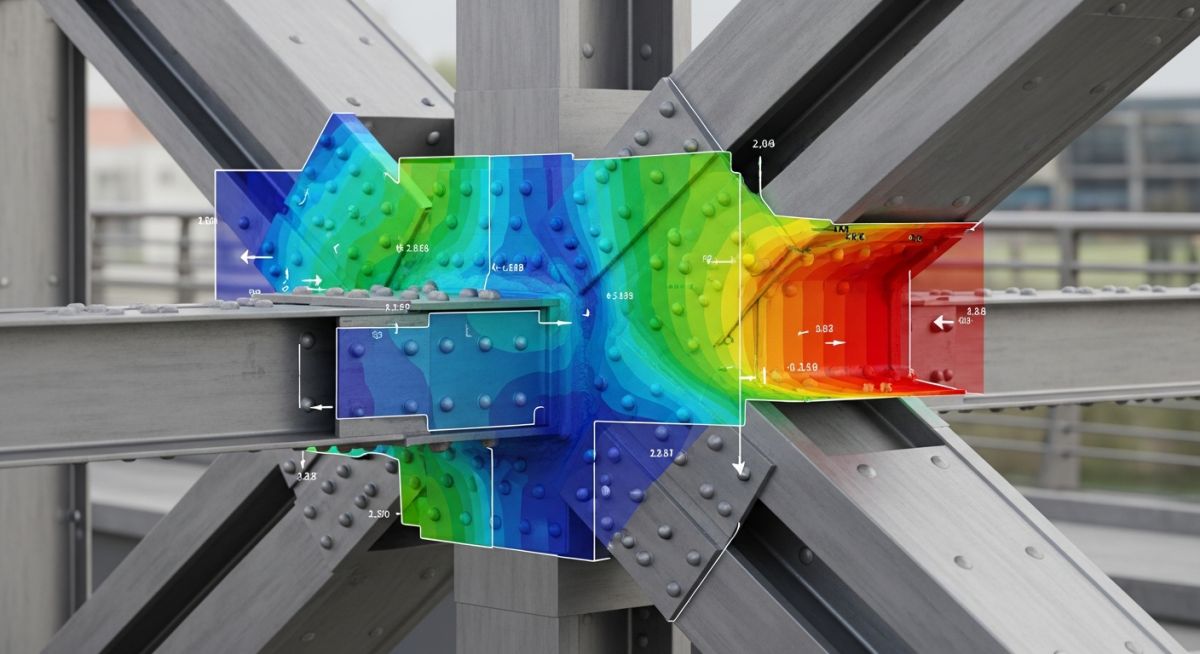
What is the Factor of Safety?
Structural Safety Margin: The structural design ratio representing the structural capacity of a system relative to its actual applied load, ensuring compliance with ASME Section VIII and AISC 360 standards.
In simple terms, the factor of safety (FoS or CoS – Coefficient of Safety) is a multiplier applied to the expected loads of a structure to ensure it can withstand unexpected stresses. If a pipe is designed to carry a fluid pressure of 100 PSI, and we apply a factor of safety of 3.0, we are engineering that pipe to withstand a theoretical pressure of 300 PSI before failure occurs.
Why do we do this? Because the real world is unpredictable. Material properties vary from batch to batch, environmental corrosion thins pipe walls over time, and operational upsets can cause sudden pressure spikes. By establishing a robust factor of safety, we protect human lives, prevent environmental disasters, and safeguard expensive capital equipment.
Importance of Factor of Safety
Engineering Risk Mitigation: The application of design multipliers to account for material imperfections, environmental degradation, and unpredictable operational overloads.
Without a calculated safety factor, engineering designs would exist on a knife-edge. The slightest material defect, such as a microscopic void in a steel casting, would result in immediate structural failure under normal operating conditions.
In my field work, I emphasize that the factor of safety is not a “fudge factor” to cover up lazy engineering. It is a rigorous, mathematically structured buffer that accounts for:
- Material Variability: Differences in yield and ultimate tensile strength across different steel heats.
- Environmental Degradation: Wall thinning due to localized pitting, stress corrosion cracking, and general atmospheric rust.
- Dynamic Loading: Water hammer, wind loads, seismic events, and mechanical vibrations from pumps and compressors.
- Consequences of Failure: The potential loss of human life or severe environmental contamination if a high-pressure toxic gas line ruptures.
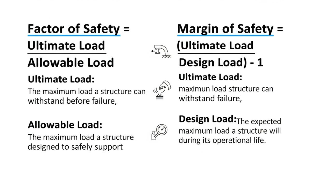
Factor of Safety Equation and Formula
Factor of Safety Formula: The mathematical expression dividing ultimate material strength by allowable design stress to establish structural integrity under peak operating conditions.
Factor of safety = Ultimate Load (Strength) / Allowable Load (Stress)
Ultimate Strength Ratio: The fundamental equation dividing the ultimate material strength by the allowable design stress to determine structural integrity.
To calculate the factor of safety, we compare the maximum capacity of the material to the actual stress it will experience. The basic mathematical formula is written as:
Where:
– FoS = Factor of Safety (dimensionless ratio)
– S_ultimate = Ultimate Tensile Strength (or Yield Strength, depending on design criteria)
– S_allowable = Allowable Design Stress (the actual stress experienced under working loads)
Let us look at a practical example. Suppose we are using ASTM A36 structural steel for a piping support bracket. The yield strength (S_y) of A36 steel is 250 MPa. If our structural analysis shows that the maximum bending stress under full operating load is 100 MPa, we calculate the factor of safety as:
This means the support bracket is engineered to handle 2.5 times the maximum expected operational load before it begins to permanently deform (yield).
The margin of safety = (Factor of safety – 1)
Margin of Safety Equation: The structural calculation subtracting one from the factor of safety to represent the excess capacity of a component.
In aerospace engineering and high-precision mechanical design, we often refer to the Margin of Safety (MoS). The margin of safety represents the excess capacity of a structure. The formula is:
If the Margin of Safety is exactly 0, the component is operating exactly at its limit (FoS = 1.0). If the Margin of Safety is positive (e.g., 0.5), the component has 50% excess capacity. If the Margin of Safety is negative (e.g., -0.1), the design is unsafe and will fail under the specified loads.
I have seen junior engineers make the dangerous mistake of using Ultimate Tensile Strength (S_u) instead of Yield Strength (S_y) when calculating safety factors for ductile metals. If a structural component yields, it permanently deforms, which can misalign piping systems, cause flange leaks, and destroy equipment. Always clarify whether your governing code requires safety factors based on yield strength or ultimate tensile strength.
Selecting the correct safety factor depends heavily on the industry, material predictability, and the consequences of structural failure. The table below outlines typical industry standards that I have applied across various engineering disciplines.
| Application / Industry | Typical FoS Range | Primary Material | Governing Code / Standard |
|---|---|---|---|
| Process Piping Systems | 3.0 – 4.0 | Carbon Steel / Stainless Steel | ASME B31.3 |
| Pressure Vessels | 3.5 – 4.0 | Low Alloy Steels | ASME Section VIII Div 1 |
| Structural Steel Buildings | 1.67 – 2.0 | ASTM A36 / A992 Steel | AISC 360 |
| Elevators & Lifts | 10.0 – 12.0 | High-Strength Wire Rope | ASME A17.1 |
| Aerospace Components | 1.15 – 1.5 | Titanium / Carbon Composites | NASA-STD-5001 |
To ensure complete alignment across engineering teams, this matrix maps core technical entities, structural acronyms, physical parameters, and their governing standard references.
| Technical Entity | Acronym | Physical Parameter | Governing Standard Reference |
|---|---|---|---|
| Yield Strength | S_y | Stress at 0.2% plastic strain offset | ASTM A370 |
| Ultimate Tensile Strength | S_u | Maximum engineering stress on curve | ASTM E8 / E8M |
| Allowable Stress | S_a | Maximum permissible design stress | ASME BPVC Section II Part D |
| Margin of Safety | MoS | Excess capacity ratio (FoS – 1) | AIAA-S-110-2005e |
Factors Affecting Factor of Safety Selection
Design Variable Assessment: The systematic evaluation of material homogeneity, environmental degradation, and load predictability to establish an appropriate structural design margin.
Before finalizing any engineering design, I require my team to run through a rigorous verification process. Selecting a safety factor that is too low can lead to catastrophic failure, while selecting one that is too high results in excessive material costs and heavy, unconstructible designs.
Field Verification Checklist
-
Material Homogeneity: Has the material been tested and certified? Cast iron and composites require higher safety factors (3.0 – 5.0) than highly predictable ductile steels (1.5 – 2.0).
-
Environmental Exposure: Will the component operate in a corrosive, high-temperature, or cryogenic environment? If yes, apply a corrosion allowance and increase the safety factor by at least 25%.
-
Load Predictability: Are the loads static, dynamic, or cyclic? Cyclic loads induce fatigue, requiring a fatigue-specific safety factor calculation under ASME Section VIII Division 2.
-
Consequence of Failure: If this component fails, is there a risk of injury or loss of life? Elevators, cranes, and high-pressure steam lines require safety factors ranging from 5.0 to 12.0.
-
Inspection Frequency: Will this component be regularly inspected using Non-Destructive Testing (NDT) methods? Infrequently inspected systems require higher safety margins.
Examples of Factors of Safety
Practical Design Applications: Real-world implementations of safety multipliers across diverse engineering disciplines to prevent catastrophic structural failures.
Using a Factor of Safety Calculator
Automated Design Verification: The utilization of digital computation tools to rapidly evaluate stress ratios and verify compliance with structural codes.
Field Case Study: Real-World Application
During a routine turnaround at a major petrochemical facility, our inspection team discovered severe fatigue cracking in a primary structural support bracket holding a high-pressure steam line. The line operated at 650°F (343°C) and 600 PSI. The original design team had applied a standard static factor of safety of 1.5 based on the yield strength of ASTM A36 steel. However, they failed to account for thermal cycling and dynamic vibrations caused by downstream control valves. The actual stress during startup cycles exceeded the allowable limits, leading to localized plastic deformation and rapid fatigue crack propagation.
I stepped in to lead the root cause analysis. We recalculated the system using a dynamic factor of safety of 3.5, incorporating fatigue strength reduction factors from ASME Section VIII Division 2. We replaced the rigid support bracket with a spring-loaded variable hanger to allow for thermal expansion. The recalculated allowable stress was reduced from 166 MPa to 71 MPa. Over the last five years of continuous operation, acoustic emission monitoring has confirmed zero crack initiation, and the system remains completely stable.
My direct recommendation from this field experience is clear: never treat dynamic systems as static. If your system experiences temperature fluctuations or mechanical vibrations, a standard static factor of safety of 1.5 or 2.0 is highly likely to fail. Always design for the worst-case transient operating conditions.
Frequently Asked Engineering Questions
What is the difference between Factor of Safety and Margin of Safety?
Why does the aerospace industry use lower factors of safety than civil engineering?
How does temperature affect the selection of a factor of safety?
Can a factor of safety be less than 1.0?
Which ASME code governs the factor of safety for pressure vessels?
How do dynamic loads impact the calculation of the factor of safety?

📚 Recommended Resources: factor of safety
Read these Guides
🎓 Advanced Training


Related posts:
![Comparison of high viscosity honey and low viscosity water pouring to demonstrate fluid resistance]()
Understanding Newton's Law of Viscosity and Key Fluid Flow Factors
![A puddle flange installed on a PVC pipe embedded in a concrete wall cross-section]()
What is a Puddle Flange? Types, Applications, and Key Advantages
![Chemical injection system administering corrosion inhibitors to a steel pipeline in an oil and gas facility.]()
Comprehensive Guide to Corrosion Inhibitors in the Oil and Gas Industry
![A metallic two-hole pipe strap securing a copper pipe to a wooden wall beam.]()
What is a Pipe Strap? Its Types, Importance, Materials, Applications
![Heavy-duty vertical pipe support riser clamps installed on steel piping through concrete floors.]()
How to Design and Install Vertical Pipe Support Systems
![Industrial piping system suspended from a ceiling using various types of pipe hanger supports.]()
How to Select and Design Pipe Hanger Supports for Industrial Piping