Table of Contents
How to Master the Free Body Diagram in Engineering Analysis
In my 20 years of designing high-pressure piping systems and heavy industrial structures, I have seen brilliant engineers fail at complex finite element analysis (FEA) simply because they skipped a basic step. They did not draw a proper free body diagram. It is easy to trust modern software, but if your boundary conditions and force vectors are wrong in your head, they will be wrong in your simulation.
I remember a project where a massive steam line support kept buckling during thermal cycles. The design team had modeled the support as a simple rigid anchor in their software. When I sat down with a pencil and drew a physical sketch of the isolated pipe segment, the issue became obvious. We had completely ignored the friction force vector acting along the pipe axis. That simple sketch saved us millions in potential downtime.
- Always isolate the system from its physical surroundings before applying force vectors.
- Never assume a support is perfectly rigid without verifying its physical stiffness and boundary conditions.
- Ensure your coordinate system is clearly defined before resolving force components.
Complete Course on
Piping Engineering
Check Now
Key Features
- 125+ Hours Content
- 500+ Recorded Lectures
- 20+ Years Exp.
- Lifetime Access
Coverage
- Codes & Standards
- Layouts & Design
- Material Eng.
- Stress Analysis
How to Construct a Free Body Diagram Correctly
To build a mathematically sound model, you must follow a strict sequence. Skipping any of these steps introduces errors that propagate through your shear and bending moment calculations.
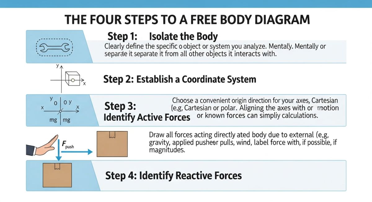
Step 1: Isolate the Body
Identify the specific component you need to analyze. Draw its outline simplified as a single line, a beam, or a rigid block. Remove all surrounding structures, supports, and connections. The body must float in your sketch, completely free from its physical environment.
Step 2: Establish Your Coordinate System
Define a clear Cartesian coordinate system (X, Y, Z). This is not just a formality. Without a defined coordinate system, assigning positive and negative signs to your force vectors becomes chaotic, leading to sign errors in your equilibrium equations.
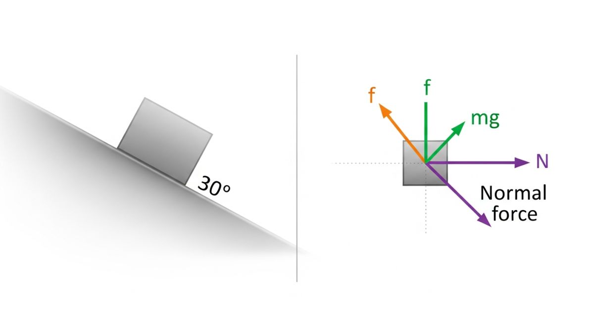
Step 3: Apply Known External Forces
Draw vectors representing all known forces acting on the body. This includes gravity (acting through the center of mass), wind loads, fluid pressures, and pre-tensioned bolts. Label each vector with its magnitude and direction angle.
Step 4: Replace Supports with Reaction Forces
This is where most mistakes happen. You must replace every physical support you removed in Step 1 with the corresponding reaction forces and moments it exerts on the body. For example, a pinned support restricts translation in X and Y, so you must draw reaction forces R_x and R_y. A fixed support restricts translation and rotation, requiring R_x, R_y, and a reaction moment M.
In my field audits, I often find engineers modeling piping guides as rigid anchors. This mistake artificially inflates the calculated reaction forces, leading to massive, expensive support structures that are completely unnecessary. Always match your mathematical reactions to the actual physical degrees of freedom of the support.
Practical Engineering Calculation Example
Let us calculate the reaction forces for a cantilevered pipe support bracket holding a heavy valve. The bracket is a steel beam of length L = 1.5 meters, welded to a structural column. The valve exerts a downward point load P = 12 kN at the very tip of the bracket. The self-weight of the bracket is represented as a uniform load w = 0.5 kN/m.
To find the reaction force (R_y) and reaction moment (M_A) at the welded connection (Point A), we apply the equations of static equilibrium:
R_y – w * L – P = 0
R_y – (0.5 kN/m * 1.5 m) – 12 kN = 0
R_y – 0.75 kN – 12 kN = 0
R_y = 12.75 kN (acting upward)
2. Sum of Moments about Point A (ΣM_A = 0):
M_A – (w * L * (L / 2)) – (P * L) = 0
M_A – (0.5 kN/m * 1.5 m * 0.75 m) – (12 kN * 1.5 m) = 0
M_A – 0.5625 kN-m – 18 kN-m = 0
M_A = 18.56 kN-m (counter-clockwise reaction)
These calculated values are used directly to size the structural weld at Point A in compliance with AWS D1.1 structural welding codes.
| Support Type | Translational DOF | Rotational DOF | Reaction Forces | Typical Application |
|---|---|---|---|---|
| Fixed Anchor | Restrained (X, Y, Z) | Restrained (X, Y, Z) | 3 Forces, 3 Moments | Piping battery limits, vessel nozzles |
| Pinned / Hinge | Restrained (X, Y, Z) | Free (X, Y, Z) | 3 Forces, 0 Moments | Truss joints, structural column bases |
| Roller Support | Restrained (Vertical) | Free (X, Y, Z) | 1 Force (Vertical) | Bridge expansion joints, pipe sleepers |
| Guided Support | Restrained (Lateral) | Free (Axial) | 2 Forces (Lateral) | Long straight pipe runs |
| Entity / Acronym | Physical Parameter | Governing Standard | Analytical Purpose |
|---|---|---|---|
| FBD | Force & Moment Vectors | ASME B31.3 | Isolating system boundaries for stress analysis |
| DOF | Degrees of Freedom | AISC 360 | Defining boundary constraints in structural nodes |
| FEA | Stiffness Matrix & Mesh | ASME Section VIII | Numerical validation of complex stress profiles |
Verifying Your Free Body Diagram on Site
Before signing off on any structural or piping design, I perform a physical walkdown. You must verify that what was drawn on paper matches what was built in the field. Use this checklist during your next site inspection.
-
Verify Support Clearances: Ensure guided supports have the specified physical gap (typically 1.5 mm to 3 mm) to allow axial movement without binding.
-
Inspect Spring Hanger Travel: Confirm that spring hangers are set to their cold load positions and that travel stops have been removed before commissioning.
-
Check Anchor Bolt Torque: Verify that structural baseplate anchor bolts are torqued to design specifications to prevent rotational slip.
-
Validate Friction Coefficients: Ensure slide plates (PTFE or graphite) are clean, level, and free of paint overspray that could increase friction forces.
Field Case Study: Real-World Application
At a major petrochemical facility, a 24-inch cooling water header was experiencing severe vibration during pump startup. Within six months, the welds on the primary anchor support began to crack. The original design team had modeled the system as a static load case, completely omitting the dynamic hydraulic transient forces (water hammer) from their initial free body diagram.
I was brought in to lead the forensic engineering team. We redrew the free body diagram of the header, adding the transient force vector (F = ΔP * A) calculated from the fluid velocity change. This revealed a dynamic force of 45 kN acting axially on the pipe. We redesigned the support system by replacing the rigid anchor with a dynamic snubber support, which absorbed the transient shock while allowing normal thermal expansion. The cracking stopped immediately.
My direct recommendation to all design leads: never treat dynamic systems as purely static. If your system contains fast-acting valves or high-capacity pumps, your analytical model must include dynamic force vectors.
Common Questions on Free Body Diagram Methods
How do you handle internal forces in a free body diagram?
What is the difference between a free body diagram and a kinetic diagram?
How do friction forces change the FBD in dynamic piping systems?
Why are thermal expansion forces modeled as external forces on a piping FBD?
How does ASME B31.3 govern the load combinations derived from an FBD?
Can a free body diagram be used for non-rigid, deformable bodies?
===FAQ_BLOCK===

📚 Recommended Resources: free body diagram
Read these Guides
🎥 Watch Tutorials

Related posts:
![Mastering ASME BPVC Creep Design for High Temperature Vessels]()
Mastering ASME BPVC Creep Design for High Temperature Vessels
![What is Corrosion Under Insulation and How to Prevent It]()
What is Corrosion Under Insulation and How to Prevent It
![What is ASME B31.3 Pressure Leak Test Requirements]()
What is ASME B31.3 Pressure Leak Test Requirements
![What is the Minimum Distance Between Welds in Piping?]()
What is the Minimum Distance Between Welds in Piping?
![How Buried Pipeline Stress Analysis Coating Factor Impacts Piping Integrity]()
How Buried Pipeline Stress Analysis Coating Factor Impacts Piping Integrity
![Understanding the GRE Design Envelope for Safe Piping Operations]()
Understanding the GRE Design Envelope for Safe Piping Operations