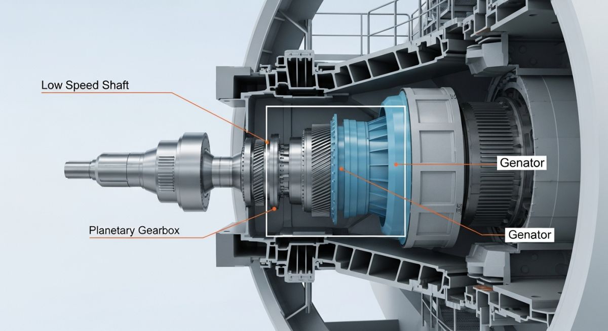
Wind Turbine Generators Explained: Engineering Design and Selection
In my two decades of experience within the energy infrastructure sector, I have observed that the heart of any wind farm is not just the blade profile, but the generator architecture. Selecting the correct machine—whether an induction, synchronous, or permanent magnet generator—dictates the entire project’s lifecycle cost and grid compliance profile.
Engineers often overlook the subtle interplay between the drivetrain’s mechanical torque and the generator’s electromagnetic response. This guide dissects these complexities, providing you with the technical foundation to optimize your next renewable energy project design.
Key Engineering Takeaways:
- Understand the torque-speed characteristics of Doubly Fed Induction Generators (DFIG).
- Evaluate the impact of Permanent Magnet Generator (PMG) efficiency on low-wind performance.
- Master the grid-code requirements for reactive power compensation in modern turbine arrays.
- Learn to mitigate harmonic distortion through advanced power electronics integration.
Technical Analysis of Wind Turbine Generators
Wind Turbine Generators Engineering: These systems utilize electromagnetic induction to convert mechanical rotational energy into electrical energy, requiring precise control of flux density and rotor slip to maintain frequency stability.
The selection of a generator type is fundamentally a trade-off between mechanical complexity and power electronics requirements. In my experience, the Doubly Fed Induction Generator (DFIG) remains the industry workhorse due to its ability to operate over a wider speed range compared to fixed-speed induction machines. The DFIG allows for independent control of active and reactive power by feeding the rotor circuit through a partial-scale power converter, typically rated at 25-30% of the total generator capacity.
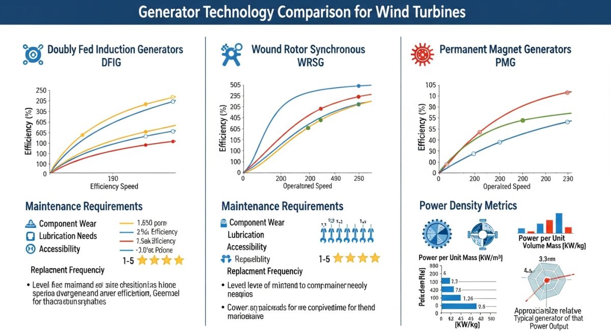
Electromagnetic Design Parameters
When calculating the power output, we must account for the mechanical power input P = 0.5 * rho * A * v^3 * Cp, where rho is air density, A is swept area, v is wind speed, and Cp is the power coefficient. The generator must be sized to handle the peak torque at the rated wind speed while maintaining thermal limits defined by NEMA MG 1 standards.
Field Warning: Thermal Derating
Always account for ambient temperature fluctuations in your nacelle cooling design. A generator rated for 25 degrees Celsius will experience significant derating if the internal nacelle temperature exceeds 40 degrees Celsius, potentially leading to premature insulation failure in the stator windings.
Permanent Magnet Generators (PMGs) have gained traction in offshore applications where maintenance access is restricted. By eliminating the need for excitation current and slip rings, PMGs reduce mechanical wear. However, they require a full-scale power converter to decouple the generator frequency from the grid frequency, which increases the complexity of the electrical balance of plant.
For synchronous generators, the excitation system must be robust enough to handle transient grid faults. We often utilize brushless excitation systems to minimize maintenance intervals. The synchronization process requires precise control of the phase angle, voltage magnitude, and frequency to prevent severe mechanical stress on the gearbox during grid connection.
Generator Performance Trade-offs: Evaluating the operational benefits and technical limitations of various generator topologies is essential for ensuring long-term asset reliability and grid compliance.
Advantages
- DFIG systems offer reduced converter costs by handling only a fraction of total power.
- PMG designs eliminate excitation losses, significantly improving efficiency at partial loads.
- Synchronous generators provide inherent reactive power support for grid voltage regulation.
- Direct-drive configurations remove gearbox failure points, lowering long-term O&M expenditure.
- Variable speed operation maximizes aerodynamic efficiency across varying wind regimes.
Disadvantages
- DFIGs require complex slip ring maintenance and are susceptible to grid fault sensitivity.
- PMG systems involve high-cost rare-earth magnets, increasing initial capital expenditure.
- Full-scale converters for PMGs introduce additional harmonic distortion risks to the grid.
- Synchronous machines require complex synchronization logic to avoid mechanical torque spikes.
- High-speed gearboxes in induction systems remain a primary source of mechanical fatigue.
Industrial Wind Integration: Modern wind turbine generators are deployed across diverse environments, each requiring specific electrical and mechanical configurations to meet site-specific load demands.
Utility-Scale Onshore Wind Farms
These projects typically utilize DFIG or PMG architectures to balance cost and efficiency. The integration requires robust substation design to manage the aggregated output of multiple turbines while adhering to strict grid interconnection codes for frequency response.
Offshore Deep-Water Installations
Reliability is the primary driver here, favoring direct-drive PMG systems to minimize maintenance in harsh marine environments. The electrical design must account for long-distance subsea transmission and the associated reactive power compensation requirements.
Microgrid and Remote Power Systems
Small-scale wind generators often employ permanent magnet technology to provide stable power in isolated locations. These systems frequently integrate battery energy storage to smooth out the inherent intermittency of wind-driven generation.
Industrial Feedstock Decarbonization
Large manufacturing facilities are increasingly installing dedicated wind assets to offset carbon footprints. These installations require sophisticated power management systems to ensure the wind generation aligns with the facility’s real-time electrical load profile.
Selecting the appropriate generator topology requires a deep understanding of how electrical output characteristics align with grid requirements and mechanical drive train constraints. In my experience, the choice between induction, synchronous, and permanent magnet generators (PMG) is rarely about peak efficiency alone; it is fundamentally about the trade-off between control complexity, maintenance intervals, and the ability to provide ancillary grid services like reactive power support.
The following table summarizes the critical performance metrics for common generator types used in modern wind energy conversion systems. Note that while induction generators are historically favored for their ruggedness and low cost, the industry has shifted toward PMG systems for offshore applications where maintenance accessibility is severely limited and high power density is required to minimize nacelle weight.
| Generator Type | Excitation Source | Speed Control | Maintenance Needs | Grid Compliance |
|---|---|---|---|---|
| Squirrel Cage Induction | Grid-fed | Fixed | Low | Limited |
| Doubly Fed Induction (DFIG) | Rotor-fed | Variable | Moderate | High |
| Permanent Magnet (PMG) | Rare Earth Magnets | Full Variable | Very Low | Excellent |
Engineers must evaluate these parameters against the specific site wind profile. For instance, a site with high turbulence intensity may favor the mechanical damping characteristics of a DFIG system, whereas a stable, high-wind offshore site will almost certainly benefit from the high efficiency and reduced gearbox requirements of a direct-drive PMG configuration.
To effectively manage the integration of wind turbine generators into a power system, one must map the physical components to their respective electrical standards and control architectures. This matrix provides a structural overview of the key entities involved in generator design, from the electromagnetic core to the power electronics interface that ensures compliance with IEEE and IEC grid codes.
Understanding these relationships is vital for troubleshooting harmonic distortion, voltage stability, and thermal management issues during the commissioning phase of a wind farm project. By aligning these technical entities, engineers can better predict system behavior under transient grid conditions, such as low-voltage ride-through (LVRT) events.
| Entity | Function | Standard Reference |
|---|---|---|
| Power Converter | AC-DC-AC Conversion | IEC 61400-21 |
| Stator Winding | Electromagnetic Induction | NEMA MG 1 |
| Rotor Assembly | Magnetic Flux Generation | ISO 1940-1 |
The matrix serves as a foundational reference for procurement and quality assurance. When reviewing vendor documentation, ensure that the specified generator components meet the rigorous insulation and thermal cycling requirements defined by these international standards to prevent premature failure in harsh environmental conditions.
Verification of wind turbine generator performance requires a systematic approach to ensure that the installed hardware matches the design specifications and grid connection requirements. In my experience, the most common failures during the first year of operation stem from inadequate alignment of the generator shaft or improper cooling system configuration, both of which can be mitigated through a rigorous pre-commissioning checklist.
Generator Installation & Validation Protocol
- ✅ Shaft Alignment: Verify laser alignment of the generator shaft to the gearbox output to within 0.05mm tolerance.
- ✅ Insulation Resistance: Perform a Megger test on stator windings; values must exceed 100 Megaohms at 1000V DC.
- ✅ Cooling System: Confirm coolant flow rates and pressure levels match the manufacturer’s IEC 60034-5 specifications.
- ✅ Converter Sync: Validate the power converter’s ability to synchronize with the grid frequency within 0.1Hz.
- ✅ Vibration Analysis: Conduct a baseline vibration spectrum analysis to identify potential bearing defects before full load operation.
Beyond these physical checks, ensure that the control software is updated to the latest firmware version, as many modern grid-code compliance features are implemented via software-defined logic. Document every test result in a centralized database to facilitate long-term predictive maintenance and warranty claims. If any parameter falls outside the specified range, do not proceed to full-load testing until the root cause is identified and rectified by the site engineering team.
Problem: Premature Stator Insulation Breakdown
A 3MW wind farm experienced repeated stator insulation failures within the first 18 months of operation, leading to significant downtime and revenue loss.
- Excessive harmonic content from the power converter causing localized overheating.
- Inadequate ventilation in the nacelle leading to ambient temperatures exceeding 50 degrees Celsius.
- Failure to maintain the cooling fluid purity, resulting in conductive sediment buildup.
- Improper grounding of the generator frame causing circulating currents in the bearings.
Outcome: System Reliability Restoration
By implementing a comprehensive remediation strategy, the site achieved a 98% availability rate over the subsequent three-year period.
- Installation of active harmonic filters to reduce total harmonic distortion (THD) below 5%.
- Upgraded the cooling system with a closed-loop heat exchanger and high-efficiency pumps.
- Implemented a quarterly oil and coolant analysis program to detect early signs of contamination.
- Retrofitted insulated bearings to eliminate shaft current damage.
The recommendation for future projects is to prioritize thermal management and harmonic mitigation during the design phase. Do not treat the generator as an isolated component; it must be viewed as part of an integrated electrical system where the converter, cabling, and cooling infrastructure are equally critical to the longevity of the asset.
Why are Permanent Magnet Generators preferred for offshore wind?
- Elimination of excitation losses, leading to higher efficiency at partial loads.
- Reduced maintenance requirements due to the absence of slip rings or brushes.
- Ability to operate at lower speeds, allowing for direct-drive configurations that remove the need for a complex gearbox.
- Enhanced reliability in harsh, corrosive offshore environments where gearbox failures are costly to repair.
How does the power converter impact generator longevity?
- High-frequency switching can induce voltage spikes that degrade stator insulation over time.
- Improperly filtered output leads to harmonic currents that cause excessive heating in the rotor and stator cores.
- Advanced control algorithms in modern converters can actually extend generator life by smoothing torque ripples and reducing mechanical fatigue.
- Engineers must ensure that the converter’s pulse-width modulation (PWM) frequency is compatible with the generator’s insulation class as defined in IEC 60034-18.
What is the role of reactive power in wind generators?
- Induction generators typically consume reactive power, requiring external capacitor banks or power electronics to maintain grid voltage.
- Synchronous and PMG systems can be controlled to either generate or absorb reactive power, providing essential ancillary services to grid operators.
- This capability is increasingly mandated by grid codes to prevent voltage collapse during transient disturbances.
- The converter control system must be tuned to provide dynamic reactive power response, often referred to as STATCOM-like functionality.
How do I select the right generator for a specific wind site?
- Analyze the wind speed distribution (Weibull distribution) to determine the capacity factor and expected energy yield.
- Evaluate the grid connection requirements, specifically the need for low-voltage ride-through (LVRT) and reactive power support.
- Consider the accessibility of the site; remote or offshore locations necessitate high-reliability, low-maintenance designs like PMGs.
- Factor in the total cost of ownership, including the cost of power electronics and potential gearbox maintenance over a 20-year lifespan.
What are the main challenges with DFIG systems?
- The use of slip rings and brushes requires regular inspection and replacement, which is a significant maintenance cost.
- DFIGs are sensitive to grid faults, often requiring complex protection schemes to prevent damage to the rotor-side converter.
- They are less efficient than full-converter PMG systems at very low wind speeds.
- Despite these challenges, they remain a cost-effective solution for many onshore wind projects where maintenance access is relatively straightforward.
How does temperature affect generator performance?
- High temperatures increase winding resistance, leading to higher copper losses and reduced efficiency.
- Thermal expansion and contraction cycles can cause mechanical stress on the stator windings, leading to insulation cracking.
- Cooling systems must be sized for the worst-case ambient temperature and maximum load conditions.
- Continuous monitoring of winding temperatures via embedded RTDs is essential for predictive maintenance and preventing catastrophic failure.
Complete Course on
Piping Engineering
Check Now
Key Features
- 125+ Hours Content
- 500+ Recorded Lectures
- 20+ Years Exp.
- Lifetime Access
Coverage
- Codes & Standards
- Layouts & Design
- Material Eng.
- Stress Analysis
