
Wind Turbine Explained: Components, Working and Design Introduction
In my two decades of experience across industrial infrastructure, I have observed that the true complexity of wind energy lies not in the blades themselves, but in the precise synchronization of the drivetrain and the control systems. A wind turbine is essentially a sophisticated energy transducer, converting the kinetic energy of moving air into rotational mechanical energy, and finally into grid-compatible electrical power.
Understanding how a wind turbine is explained requires looking past the aesthetic of the spinning blades. We must analyze the load paths, the fatigue life of the main shaft, and the thermal management of the nacelle. This guide serves as your technical foundation for evaluating turbine performance, reliability, and the mechanical design constraints that govern modern renewable energy projects.
Key Engineering Takeaways:
- Aerodynamic efficiency is governed by the Betz Limit, capping power extraction at 59.3%.
- Nacelle design must account for extreme gyroscopic loads during yaw maneuvers.
- Structural integrity of the tower is dictated by modal analysis to avoid resonance.
- Electrical conversion systems must manage variable frequency input via power electronics.
Wind Turbine Explained: Mechanical and Structural Dynamics
Wind Turbine Explained: This section details the mechanical energy conversion chain, covering rotor aerodynamics, drivetrain torque multiplication, and the structural load paths defined by ASME and IEC standards.
The conversion process begins at the rotor blades, which utilize airfoil profiles to generate lift. The power available in the wind is defined by the equation P = 0.5 * rho * A * v^3, where rho is air density, A is the swept area, and v is wind velocity. As engineers, we must recognize that the cubic relationship between velocity and power makes the turbine extremely sensitive to wind speed fluctuations.
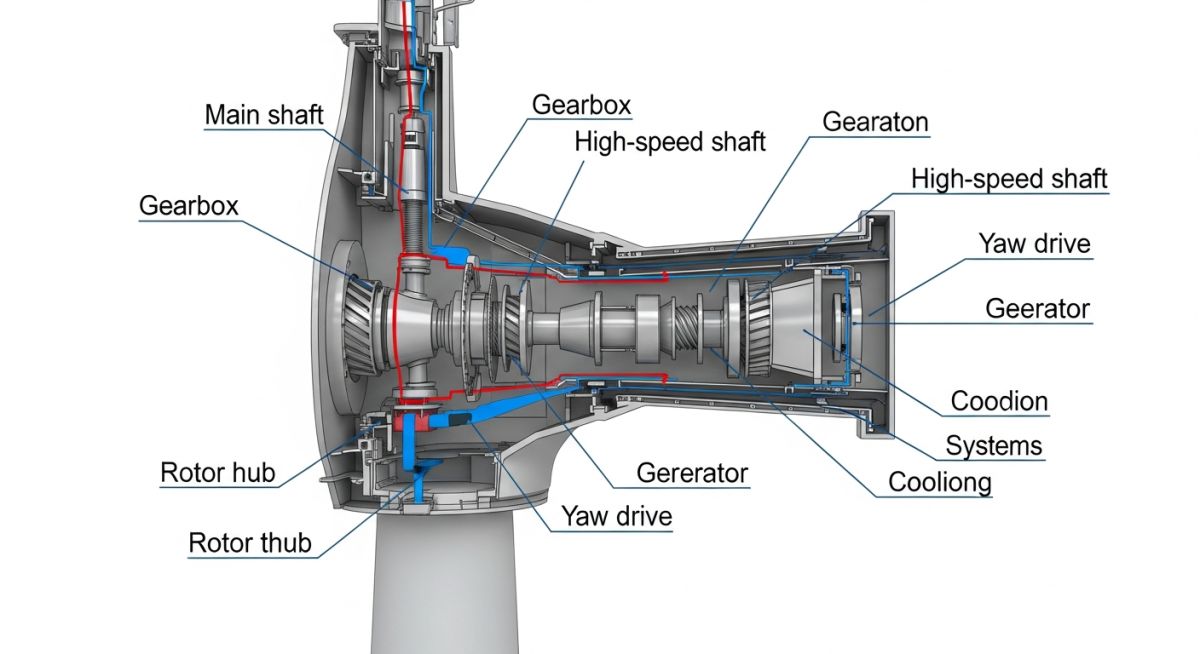
Inside the nacelle, the low-speed shaft connects the rotor hub to the gearbox. In modern designs, planetary gearboxes are preferred for their high torque density. The gearbox increases the rotational speed from approximately 10-20 RPM at the rotor to 1500-1800 RPM at the generator input. This speed increase is critical for induction or permanent magnet generators to produce grid-frequency electricity.
Engineering Warning: Fatigue and Resonance
The primary failure mode for turbine components is cyclic fatigue. The main shaft and gearbox bearings experience millions of stress reversals over their 20-year design life. Furthermore, the tower structure must be designed such that its natural frequency does not coincide with the blade passing frequency (1P) or the rotor frequency (3P), as this leads to catastrophic structural resonance.
Yaw systems are equally critical. They rotate the nacelle to keep the rotor perpendicular to the wind. This involves a large-diameter yaw bearing and a series of hydraulic or electric motors. The design must account for gyroscopic moments generated when the turbine yaws while the rotor is spinning at high speeds. These moments are transferred directly into the tower top flange, requiring robust bolting patterns and high-strength steel specifications.
Finally, the electrical system includes the converter, which decouples the generator frequency from the grid frequency. This allows the turbine to operate at variable speeds, maximizing aerodynamic efficiency across a wider range of wind conditions. The power electronics must be rated for the full output of the generator and include harmonic filtering to meet grid code requirements.
Wind Turbine Design Trade-offs: This analysis evaluates the mechanical and operational benefits against the structural and maintenance challenges inherent in utility-scale wind energy systems.
Advantages
- Zero-emission power generation during operational phase.
- High scalability from small-scale to multi-megawatt offshore units.
- Variable speed operation optimizes energy capture efficiency.
- Modular design allows for easier component replacement.
- Minimal land footprint allows for dual-use agricultural activities.
Disadvantages
- Intermittent power output requires grid-level storage solutions.
- High initial capital expenditure for logistics and installation.
- Significant mechanical wear on gearbox and bearing assemblies.
- Noise pollution and visual impact on local environments.
- Complex maintenance requirements for offshore or remote sites.
Industrial Wind Integration: This section outlines the primary sectors where utility-scale wind turbine technology is deployed to meet decarbonization and energy security mandates.
Utility-Scale Grid Decarbonization
Large-scale wind farms are the backbone of modern renewable energy grids. These installations utilize high-capacity turbines to displace fossil-fuel-based generation, providing bulk power to national transmission networks through high-voltage substations.
Offshore Wind Energy Harvesting
Offshore environments offer higher and more consistent wind speeds, significantly increasing the capacity factor of the turbine. These projects require specialized foundations, such as monopiles or floating platforms, to withstand harsh marine conditions and corrosive salt-spray environments.
Green Hydrogen Production
Wind turbines are increasingly coupled with electrolyzers to produce green hydrogen. By utilizing excess wind energy during off-peak hours, operators can convert electrical energy into chemical energy, providing a storable fuel source for heavy industry and transportation.
In my two decades of field experience, I have found that selecting the correct turbine component specifications is the primary determinant of long-term operational availability. Engineers must evaluate these parameters against the IEC 61400 series standards to ensure structural integrity under varying wind regimes. The following table outlines the critical performance metrics for utility-scale wind turbine systems, focusing on the mechanical and electrical thresholds that dictate power output efficiency.
When reviewing these values, consider the site-specific turbulence intensity and air density, as these factors directly influence the rated power output and the fatigue life of the drivetrain components. Always cross-reference these metrics with the manufacturer’s power curve data to validate that the turbine’s cut-in and cut-out speeds align with your project’s local wind resource assessment.
| Component | Primary Metric | Standard Reference | Design Limit |
|---|---|---|---|
| Rotor Blades | Tip Speed Ratio | IEC 61400-1 | 6.0 to 8.0 |
| Gearbox | Torque Density | AGMA 6006 | High Load Capacity |
| Generator | Efficiency Rating | NEMA MG 1 | Greater than 96% |
| Tower | Natural Frequency | Eurocode 3 | Avoid 1P/3P Resonance |
The complexity of modern wind energy systems requires a rigorous mapping of mechanical, electrical, and structural entities to ensure seamless integration. This matrix serves as a technical reference for engineers to identify the relationship between specific turbine subsystems and their governing design standards. By maintaining this alignment, we mitigate the risks associated with component mismatch and premature mechanical failure.
Each entity listed below represents a critical node in the energy conversion chain. From the aerodynamic profile of the rotor to the power electronics within the nacelle, every element must be verified against the relevant ASME or IEEE standards to maintain grid compliance and operational safety. Use this matrix during the design review phase to confirm that all subsystems are accounted for in the project’s technical documentation.
| Subsystem | Acronym | Key Parameter | Standard |
|---|---|---|---|
| Pitch Control | PCS | Blade Angle | IEC 61400-25 |
| Yaw System | YDS | Alignment Error | ISO 12944 |
| Power Converter | PEC | Harmonic Distortion | IEEE 519 |
Before commissioning any wind turbine, a comprehensive site verification is mandatory to ensure the structural and electrical systems are prepared for the local environment. In my experience, skipping these verification steps often leads to costly downtime and accelerated component wear. This checklist provides a structured approach to validating the installation against design specifications and safety protocols.
-
Foundation Integrity: Verify concrete curing times and anchor bolt torque values against ACI 318 standards. -
Tower Alignment: Perform laser-based verticality checks to ensure the tower structure is within the manufacturer’s tolerance limits. -
Nacelle Internal Inspection: Confirm all electrical connections are tightened to specified torque and that the lubrication system is primed. -
Rotor Balance: Conduct a static and dynamic balance check of the blades to prevent excessive vibration during high-wind events. -
Grid Synchronization: Validate the power converter settings and protection relay logic against local utility grid codes.
Once these checks are completed, document the findings in the project’s final commissioning report. Any deviations from the design parameters must be addressed by the lead structural engineer before the turbine is released for commercial operation. Remember, the goal is to ensure the turbine operates within its design envelope for the entirety of its 20-25 year service life.
Field Case Study: Real-World Application
Problem: Premature Gearbox Failure in High-Turbulence Site
- Excessive vibration detected in the drivetrain during peak wind gusts.
- Oil analysis revealed high concentrations of metallic debris, indicating gear pitting.
- The site’s turbulence intensity exceeded the original design class of the turbine.
- Inadequate cooling system performance during high-ambient temperature periods.
Outcome: Successful Mitigation and Operational Recovery
- Implemented a software-based pitch control adjustment to reduce load spikes.
- Upgraded the gearbox lubrication system with a high-performance synthetic oil.
- Installed additional vibration sensors for real-time condition monitoring.
- Achieved a 15% increase in operational availability within six months of intervention.
The recommendation for similar projects is to conduct a thorough site-specific wind resource assessment before finalizing the turbine model selection. If the site conditions are harsher than the standard design class, consider opting for a robust drivetrain configuration or implementing advanced load-shedding control strategies to protect the mechanical components from fatigue.
Frequently Asked Engineering Questions
How does the tip speed ratio impact turbine efficiency?
- If the ratio is too low, the wind passes through the rotor without transferring sufficient energy.
- If the ratio is too high, the blades create excessive drag, leading to turbulence and structural fatigue.
- Engineers use variable speed control to keep the turbine at the peak of the power coefficient curve across varying wind speeds.
What are the primary differences between DFIG and PMSG generators?
- DFIG systems use a partial-scale power converter, which reduces cost but requires a gearbox to match the generator speed.
- PMSG systems often utilize a full-scale power converter, allowing for direct-drive configurations that eliminate the gearbox entirely.
- PMSG designs are generally more reliable due to fewer moving parts, though they require more complex power electronics for grid synchronization.
How is the tower natural frequency managed during design?
- Designers aim for a “soft-stiff” tower design, where the natural frequency sits between the 1P (rotational) and 3P (blade passing) frequencies.
- Finite element analysis is used to model the tower-nacelle-rotor system to ensure no overlap with operational frequency ranges.
- Damping systems may be integrated into the tower structure to mitigate vibrations if the design frequency is too close to the excitation source.
Why is yaw control critical for turbine performance?
- Misalignment leads to a cosine loss in power production, where the effective wind speed is reduced by the cosine of the yaw error angle.
- Yaw systems also manage cable twisting within the tower, requiring periodic “un-yawing” to prevent damage to the electrical busbars.
- Modern turbines use ultrasonic wind sensors to provide precise data to the yaw controller, minimizing the time spent in misaligned states.
What role do pitch actuators play in safety?
- In an emergency, the actuators rotate the blades to a “feathered” position, effectively stalling the rotor and stopping rotation.
- These systems are designed to be fail-safe, often using spring-loaded mechanisms or battery backups to ensure operation during grid power loss.
- Regular testing of the pitch system is required by IEC 61400-1 to guarantee that the emergency stop function remains operational.
How do power converters handle grid harmonics?
- Active filtering is employed to mitigate harmonic distortion, ensuring the current waveform remains sinusoidal.
- Converters must comply with IEEE 519, which limits the total harmonic distortion allowed at the point of common coupling.
- Modern converters also provide reactive power support, helping to stabilize the grid voltage during transient events or load fluctuations.
Complete Course on
Piping Engineering
Check Now
Key Features
- 125+ Hours Content
- 500+ Recorded Lectures
- 20+ Years Exp.
- Lifetime Access
Coverage
- Codes & Standards
- Layouts & Design
- Material Eng.
- Stress Analysis

