Table of Contents
What is Static Equipment? Types and List of Static Equipments
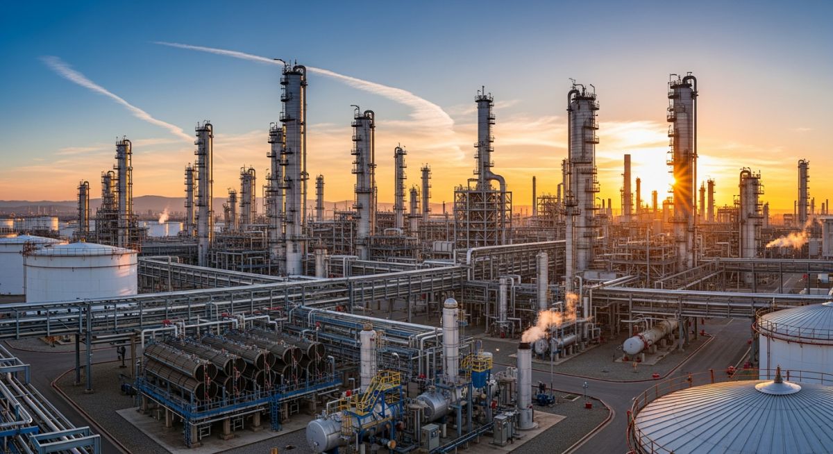
Over my 20 years in piping and process engineering, I have walked through hundreds of hydrocarbon processing facilities, chemical plants, and power generation stations. While rotating machinery like pumps and compressors often grab the spotlight with their high-speed hums, the silent giants—the static equipment—form the true physical backbone of any process plant. These stationary units operate under extreme pressures, cryogenic temperatures, and highly corrosive environments without a single moving part. Understanding how to select, design, and maintain these assets is what separates a standard plant design from a highly reliable, safe, and profitable operation.
Key Engineering Takeaways
- Code Compliance: Every piece of static equipment must align with international standards such as ASME Section VIII for pressure vessels and API 650 for storage tanks.
- Structural Integrity: Design calculations must account for internal/external pressure, wind loads, seismic forces, and thermal expansion.
- Material Selection: Choosing the correct metallurgy (e.g., carbon steel, stainless steel, duplex, or exotic alloys) is critical to combat corrosion and high-temperature degradation.
- Lifecycle Management: Regular inspection, non-destructive testing (NDT), and fitness-for-service evaluations keep these massive assets operating safely past their design life.
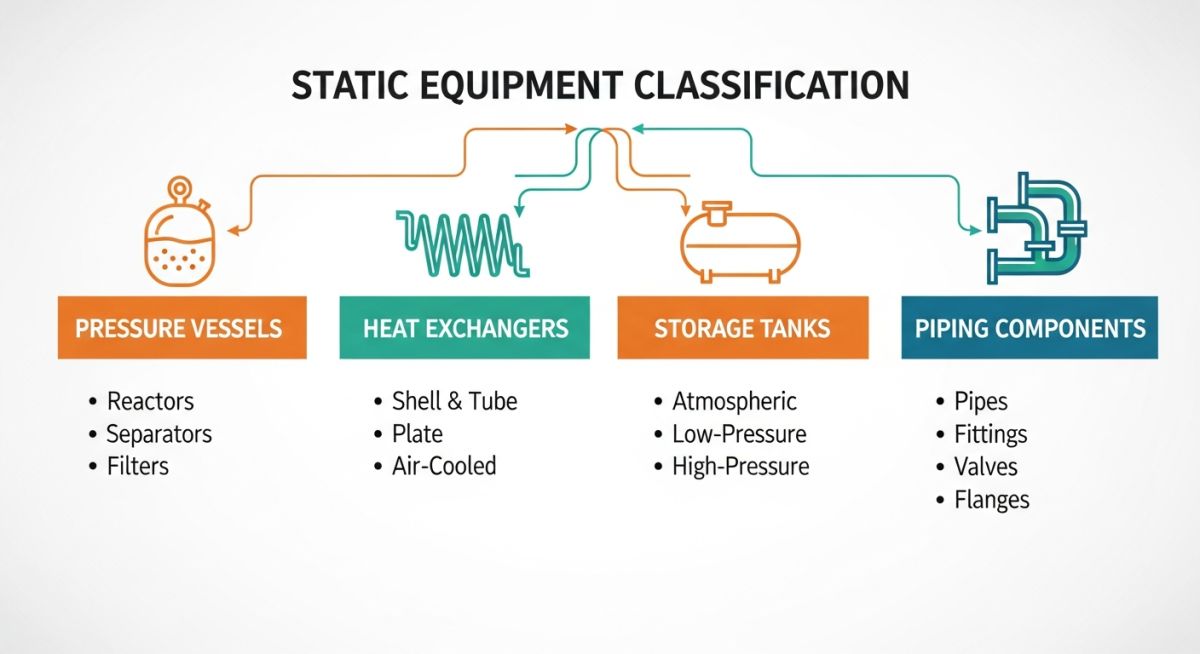
How Do We Classify Static Equipment in Plants?
In my experience, classifying static equipment correctly at the start of a project dictates the entire engineering workflow. It determines which design codes apply, which software tools we use (such as PV Elite or Compress), and what level of quality control is required during fabrication. Let us break down the primary categories of static equipment that you will encounter on any process plant layout.
1. Pressure Vessels
Pressure vessels are leak-tight containers designed to hold liquids or gases at a pressure substantially different from the ambient pressure. They are designed in accordance with ASME Section VIII Division 1 or Division 2.
To calculate the minimum required thickness of a cylindrical shell under internal pressure, we use the standard ASME formula:
Where:
• t = Minimum required shell thickness (inches)
• P = Internal design pressure (psi)
• R = Inside radius of the shell course under consideration (inches)
• S = Maximum allowable stress value of the material (psi)
• E = Joint efficiency of the longitudinal weld (ranging from 0.70 to 1.00 based on radiography)
2. Heat Exchangers
These units facilitate the transfer of thermal energy between two or more fluids at different temperatures. The most common industrial type is the Shell and Tube Heat Exchanger, designed under TEMA Standards (Tubular Exchanger Manufacturers Association) and ASME Section VIII. Other types include Plate Heat Exchangers (PHE) and Air-Cooled Heat Exchangers (Fin-Fans).
3. Storage Tanks
Unlike pressure vessels, storage tanks typically operate at atmospheric or very low pressures. They are massive structures designed to store crude oil, intermediate products, chemicals, or water. The primary design codes are API 650 (welded tanks for oil storage) and API 620 (design and construction of large, welded, low-pressure storage tanks).
During my career, I have seen engineers focus solely on internal pressure while neglecting external environmental loads. For tall vertical columns (such as distillation towers), wind and seismic forces generate massive bending moments at the base. If the skirt support thickness and anchor bolt design are not verified for these combined stresses, structural buckling or foundation failure can occur under extreme weather conditions.
4. Industrial Chimneys and Stacks
These are vertical structures designed to discharge exhaust gases into the atmosphere at safe heights. They must withstand high thermal gradients, internal flue gas corrosion, and dynamic wind-induced vibrations (vortex shedding).
| Equipment Category | Common Equipment Type | Primary Design Code | Key Design Parameters | Common Materials |
|---|---|---|---|---|
| Pressure Vessels | Reactors, Separators, Drums, Columns | ASME Sec VIII Div 1 & 2 | Internal/External Pressure, Temperature, Corrosion Allowance | ASTM A516 Gr. 70, Stainless Steel 304/316, Clad Plates |
| Heat Exchangers | Shell & Tube, Plate, Fin-Fan Exchangers | TEMA, ASME Sec VIII, API 661 | Thermal Duty, Fluid Velocity, Pressure Drop, Tube Vibration | Carbon Steel, Copper Alloys, Titanium, Duplex SS |
| Storage Tanks | Atmospheric Tanks, Low-Pressure Tanks | API 650, API 620, API 653 (Inspection) | Hydrostatic Head, Wind/Seismic Loads, Settlement | ASTM A36, ASTM A283, Carbon Steel |
| Piping Systems | Process Piping, Utility Piping | ASME B31.3, ASME B31.1 | Thermal Expansion, Pipe Span, Support Loads, Pressure Drop | ASTM A106 Gr. B, ASTM A312 TP316, Alloy Steel |
| Technical Entity | Structural Acronym | Physical Parameters | Hyperlinked Standard Reference |
|---|---|---|---|
| Minimum Design Metal Temperature | MDMT | Lowest operating temperature to prevent brittle fracture | ASME Sec VIII UCS-66 |
| Maximum Allowable Working Pressure | MAWP | Maximum pressure at the top of a vessel in its operating position | ASME Sec VIII Div 1 |
| Post-Weld Heat Treatment | PWHT | Controlled heating to relieve residual stresses from welding | ASME Sec VIII UW-40 |
| Joint Efficiency | JE | Numerical value representing weld reliability (0.7 to 1.0) | ASME Sec VIII UW-12 |
How to Inspect Static Equipment Before Startup?
Before introducing hydrocarbons or high-pressure steam into any static equipment, a comprehensive field inspection is mandatory. In my years on site, skipping even a minor check can lead to catastrophic leaks or structural failures during startup. Use this field-verified checklist to ensure your assets are fully prepared for safe operation.
Field Verification & Inspection Checklist
-
Hydrostatic/Pneumatic Test Verification: Confirm that the pressure test has been successfully completed and documented in accordance with ASME Section VIII UG-99 or UG-100.
-
Internal Cleanliness Inspection: Verify that the vessel interior is completely free of construction debris, slag, rust, and temporary shipping braces.
-
Flange Alignment and Bolt Torque: Ensure all nozzle connections are aligned within piping tolerance limits and bolts are torqued to the specified values using calibrated torque wrenches.
-
Relief Valve (PSV) Installation: Confirm that the pressure safety valves are calibrated, tagged, and installed with the correct set pressures as per the process design.
-
Foundation and Grounding: Check that the equipment foundation is free of cracks, grout is properly cured, and grounding lugs are securely connected to the plant earthing grid.
-
Internals and Trays Alignment: For distillation columns, verify that the fractionation trays, downcomers, and distributors are level and securely bolted.
Field Case Study: Real-World Application
The Problem: Stress Corrosion Cracking in an Amine Regenerator
During a scheduled turnaround at a major gas processing plant, visual inspection and wet fluorescent magnetic particle testing (WFMPT) revealed extensive cracking along the heat-affected zones (HAZ) of the circumferential welds in an amine regenerator column. The column, fabricated from ASTM A516 Gr. 70 carbon steel, had been in service for 12 years.
Upon reviewing the original fabrication records, I discovered that while the vessel thickness met the minimum requirements of ASME Section VIII Div 1, post-weld heat treatment (PWHT) had been bypassed because the nominal thickness was below the code-mandated threshold for mandatory PWHT. The combination of high residual welding stresses and exposure to corrosive amine solvent led to severe Alkaline Amine Stress Corrosion Cracking (ASCC).
The Outcome: Successful Weld Repair and Localized PWHT
To restore the structural integrity of the column, we executed a rigorous repair procedure:
- Excavated all cracks using controlled grinding and verified complete defect removal via dye penetrant testing.
- Re-welded the joints using low-hydrogen electrodes with preheating maintained at 150 degrees Celsius.
- Performed localized post-weld heat treatment (PWHT) at 620 degrees Celsius for 2 hours to relieve residual stresses, despite the thickness not strictly requiring it by code.
- Implemented a continuous wet H2S and amine monitoring program to track corrosion rates.
The column was safely returned to service, and subsequent turnaround inspections showed zero crack propagation, saving the operator millions of dollars in unscheduled downtime and replacement costs.
My Direct Recommendation: Always specify PWHT for carbon steel equipment in sour (H2S), amine, or caustic service, regardless of the nominal wall thickness. The cost of thermal stress relief during fabrication is a fraction of the cost of field repairs and lost production.
What Are the Core Static Equipment FAQs?
What is the primary difference between static and rotating equipment?
Which design code governs pressure vessels in process plants?
Why is corrosion allowance critical in static equipment design?
What is the purpose of post-weld heat treatment (PWHT)?
How do wind and seismic loads affect vertical static equipment?
What is the difference between API 650 and API 620 storage tanks?
===FAQ_BLOCK===

📚 Recommended Resources: static equipment
Read these Guides
🎓 Advanced Training


Related posts:
![A mechanical sucker rod pumpjack operating in an oil field at sunset]()
What is Sucker Rod Pump System in Oil Production?
![Piping material engineer reviewing technical specifications on a tablet in an industrial plant.]()
How a Piping Material Engineer Drives Industrial Project Success
![Side-by-side comparison of industrial process piping and power plant steam piping systems.]()
Differences Between ASME B31.3 and B31.1: B31.3 vs B31.1
![Large industrial steel storage tank under construction with cranes and scaffolding]()
Storage Tank Construction Method Statement: Step-by-Step Engineering Guide
![Cutaway diagram of a globe control valve highlighting the internal valve trim components]()
What is a Valve Trim? Types, Components, and Selection
![Towering steel cold box structure at an industrial cryogenic air separation unit.]()
What is a Cold Box in Cryogenic Plant Systems?