Table of Contents
What is Nitrogen Blanketing? Purpose, Procedure, and Applications
In my 20+ years of piping engineering, I have seen how a single spark can turn an atmospheric storage tank into a devastating hazard. When handling volatile organic compounds or sensitive chemicals, relying on ambient air is a recipe for disaster. That is why we design robust inerting systems to displace oxygen and moisture, ensuring both asset integrity and personnel safety.
Throughout my career in petrochemical plants, I have found that a properly executed inerting strategy is the primary line of defense against internal tank explosions. By replacing the flammable fuel-air mixture with an inert gas, we effectively eliminate the oxygen leg of the fire triangle. Nitrogen is the industry standard for this application due to its clean, non-reactive nature, wide availability, and relatively low cost.
Key Engineering Takeaways
- Combustion Prevention: Keeps the oxygen concentration well below the Limiting Oxygen Concentration (LOC) required for ignition.
- Product Quality Shielding: Prevents oxidation and moisture contamination in sensitive chemicals, food products, and pharmaceuticals.
- Structural Protection: Mitigates vacuum collapse and overpressure risks through coordinated regulator and breather valve settings.
- Emission Control: Reduces product evaporation losses, helping facilities comply with strict environmental regulations.
- Corrosion Mitigation: Eliminates atmospheric oxygen and moisture, significantly slowing down internal tank shell oxidation.
Why Implement Nitrogen Blanketing in Storage Tanks?
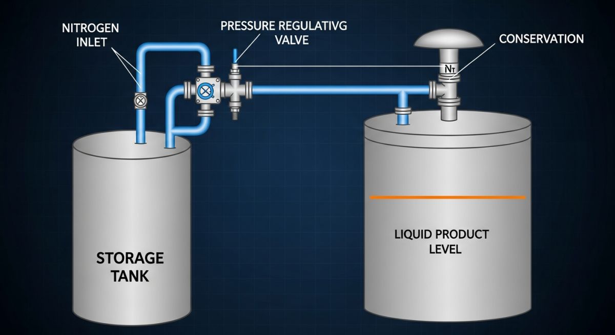
To design a safe blanketing system, we must first understand the physical and chemical dynamics inside the storage tank. When a tank is emptied, liquid level drops, creating a vacuum that draws in external air if left uncompensated. In a standard atmospheric tank, this air introduces oxygen and moisture. If the stored liquid is flammable, the vapor space quickly enters the explosive run-up range.
By utilizing a dedicated nitrogen regulator (often called a pad valve), we inject high-purity nitrogen into the vapor space as the liquid level falls. This maintains a slight positive pressure, typically between 0.5 to 2.0 inches of water column (1.25 to 5.0 mbar). This positive pressure acts as a physical barrier, preventing atmospheric air from leaking in through seals, gaskets, or open vents.
Sizing Calculations and API Standard 2000 Compliance
Sizing a blanketing system is not a matter of guesswork. We must strictly follow the guidelines laid out in API Standard 2000 (Venting Atmospheric and Low-pressure Storage Tanks). The nitrogen supply system must be sized to handle two primary flow requirements: liquid displacement (inbreathing) and thermal contraction (thermal inbreathing).
Step-by-Step Nitrogen Flow Rate Calculation:
To determine the maximum required nitrogen flow rate, we calculate the sum of the maximum liquid pump-out rate and the maximum thermal contraction rate.
-
Liquid Displacement Inbreathing (V_pd):
For every cubic meter of liquid pumped out, an equivalent volume of nitrogen must enter the tank.
V_pd = 1.015 x Q_out
Where Q_out is the maximum liquid pump-out rate in cubic meters per hour, and V_pd is the required nitrogen flow rate in normal cubic meters per hour (Nm³/h). -
Thermal Inbreathing (V_thermal):
When ambient temperatures drop rapidly (such as during a sudden rainstorm), the vapor inside the tank contracts, drawing in air or requiring immediate nitrogen makeup.
According to API 2000, for tanks with a capacity under 20,000 cubic meters, the thermal inbreathing requirement can be calculated using:
V_thermal = C x V^0.7 x Y
Where C is a factor depending on the latitude and vapor pressure, V is the tank volume in cubic meters, and Y is the temperature reduction factor. For simplified sizing, engineers often refer to API 2000 Table 4 to find direct values based on tank capacity. -
Total Required Nitrogen Supply Capacity (V_total):
V_total = V_pd + V_thermal
The nitrogen control valve must be physically capable of delivering this total flow rate at the minimum available nitrogen supply header pressure.
In my field audits, I frequently discover blanketing regulators sized only for liquid pump-out, completely ignoring thermal contraction. During a sudden summer thunderstorm, the rapid cooling of the tank shell causes instantaneous vapor contraction. If the nitrogen regulator cannot match this volumetric change, the tank will experience a vacuum condition, leading to catastrophic shell buckling or total structural collapse.
Coordinating the Pressure Control Loop
A functional blanketing system requires careful pressure coordination. We use a “pad” valve to introduce nitrogen and a “depad” valve (or vapor recovery regulator) to bleed off excess nitrogen when the tank is filled. This system must be perfectly aligned with the tank’s Pressure-Vacuum Relief Valve (PVRV) to prevent the valves from fighting each other.
If the pad valve setpoint is too close to the PVRV pressure relief setpoint, the pad valve will inject nitrogen, raise the pressure, and immediately cause the PVRV to vent. This results in massive nitrogen waste and continuous product emissions. I always recommend maintaining a minimum pressure buffer of at least 2 inches of water column (5 mbar) between the operating setpoints of the blanketing valves and the relief devices.
Standard Nitrogen Blanketing Pressure Settings
To prevent system overlap and ensure safe operation, we establish a strict pressure hierarchy. The table below outlines typical setpoints for a low-pressure storage tank designed in accordance with API Standard 650.
| Component / Device | Function | Typical Setpoint (Inches of Water Column) | Typical Setpoint (mbar) | Operational Action |
|---|---|---|---|---|
| Emergency Relief Vent (Vacuum) | Ultimate vacuum protection | -4.0 in. w.c. | -10.0 mbar | Opens to admit atmospheric air to prevent tank collapse. |
| Breather Valve (Vacuum Relief) | Primary vacuum protection | -2.0 in. w.c. | -5.0 mbar | Opens to admit air if nitrogen supply fails completely. |
| Nitrogen Pad Valve (Inlet) | Maintains inert blanket | 0.5 to 1.0 in. w.c. | 1.25 to 2.5 mbar | Opens to inject nitrogen when pressure drops below setpoint. |
| Nitrogen Depad Valve (Outlet) | Vents excess nitrogen | 2.0 to 3.0 in. w.c. | 5.0 to 7.5 mbar | Opens to bleed nitrogen to vapor recovery during tank filling. |
| Breather Valve (Pressure Relief) | Primary overpressure protection | 4.0 to 6.0 in. w.c. | 10.0 to 15.0 mbar | Vents vapor to atmosphere if depad valve fails to relieve pressure. |
| Emergency Relief Vent (Pressure) | Ultimate overpressure protection | 8.0 to 12.0 in. w.c. | 20.0 to 30.0 mbar | Opens fully to prevent catastrophic tank roof rupture. |
This matrix maps the core technical entities, structural acronyms, and physical parameters associated with industrial tank blanketing systems.
| Entity / Acronym | Technical Definition | Physical Parameter | Governing Standard |
|---|---|---|---|
| LOC / OCL | Limiting Oxygen Concentration / Oxygen Concentration Limit below which combustion cannot propagate. | Typically 5% to 10% by volume depending on hydrocarbon type. | NFPA 69 |
| PCV (Pad Valve) | Pressure Control Valve designed to regulate high-pressure nitrogen down to millibar levels. | Inlet pressures up to 10 barg; outlet pressures down to 1.25 mbar. | FCI 70-2 (Seat Leakage) |
| PVRV | Pressure Vacuum Relief Valve (Breather Valve) acting as the secondary safety barrier. | Sized for full thermal and liquid displacement flow rates. | API Standard 2000 |
| N2 Purity | The concentration of nitrogen gas required to ensure effective inerting. | 95.0% to 99.9% depending on product sensitivity to oxidation. | ISO 8573-1 (Compressed Air/Gas Quality) |
Commissioning Your Nitrogen Blanketing System
Before introducing any flammable or sensitive product into a newly blanketed tank, the entire piping loop must undergo rigorous field verification. I have developed this checklist over decades of commissioning storage terminals to ensure no critical safety step is missed.
Pre-Commissioning Field Checklist
-
Piping Hydrotest & Blowdown: Verify that the nitrogen supply line has been hydrostatically tested and thoroughly blown down with dry air to remove construction debris, slag, and moisture.
-
Regulator Calibration: Confirm that the nitrogen pad valve and depad valve have been bench-calibrated to their exact design setpoints using high-precision test gauges.
-
PVRV Inspection: Physically inspect the breather valve pallets. Ensure the shipping plastic and spacers have been removed, and that the pallets move freely on their guides.
-
Oxygen Analyzer Calibration: Calibrate the headspace oxygen analyzer (if installed) using certified span gas to ensure accurate low-oxygen alarms.
-
Isolation Valve Verification: Ensure all bypass valves around the blanketing regulators are closed and locked, and that the main nitrogen supply isolation valve is open.
-
Purge Cycle Execution: Execute a minimum of three pressure-purge cycles (pressurizing with nitrogen and venting) to reduce the initial oxygen concentration in the tank to below 1% before product introduction.
Optimizing Nitrogen Blanketing for Chemical Storage
In a chemical terminal I managed in 2024, we encountered severe operational issues with a 5,000 cubic meter toluene storage tank. The facility was experiencing massive nitrogen consumption, and the low-pressure alarm on the tank was triggering during high-rate pump-out operations, threatening to shut down the transfer pumps.
Upon field inspection, I discovered two critical design flaws. First, the nitrogen pad valve setpoint was set at 1.5 inches of water column, while the depad valve was set to open at 1.8 inches of water column. Because of this narrow 0.3-inch margin, the valves were constantly fighting each other due to normal diurnal temperature swings, venting massive volumes of nitrogen to the vapor recovery system. Second, the nitrogen supply line was restricted by an undersized 1-inch strainer, which choked the flow during maximum pump-out rates, causing the tank pressure to drop into a vacuum.
We implemented a comprehensive remediation plan:
- Widened the pressure gap: Adjusted the pad valve to 0.8 inches of water column and the depad valve to 2.5 inches of water column.
- Replaced the restricted 1-inch strainer with a high-capacity 2-inch Y-strainer to eliminate the flow restriction.
- Installed a pilot-operated blanketing regulator to provide faster response times during rapid pump-out cycles.
As a result, nitrogen consumption dropped by 42%, saving the facility over 18,000 annually in utility costs, and the vacuum alarms during pump-out were completely eliminated.
This case highlights the importance of dynamic system testing. When designing piping systems, we must look beyond static calculations and analyze how components interact under real-world transient conditions.
Frequently Asked Engineering Questions
What is the difference between tank blanketing and tank inerting?
Why is nitrogen preferred over other inert gases like carbon dioxide?
How do you calculate nitrogen consumption for a storage tank?
Can a blanketing system replace a pressure-vacuum relief valve (PVRV)?
What are the risks of nitrogen blanketing to plant personnel?
How does tank insulation affect nitrogen blanketing design?
===FAQ_BLOCK===
Complete Course on
Piping Engineering
Check Now
Key Features
- 125+ Hours Content
- 500+ Recorded Lectures
- 20+ Years Exp.
- Lifetime Access
Coverage
- Codes & Standards
- Layouts & Design
- Material Eng.
- Stress Analysis

📚 Recommended Resources: Nitrogen Blanketing
Related posts:
![Industrial worker welding a large structural steel I-beam in a fabrication facility.]()
What is Structural Steel Fabrication and How Does It Work?
![A heavy-duty stainless steel turnbuckle tensioning a structural cable.]()
What is a Turnbuckle and How to Install It?
![Stack of newly manufactured galvanized steel pipes in an industrial warehouse]()
Understanding the Galvanized Pipe Meaning in Modern Piping Systems
![Industrial Alloy 625 piping components in a manufacturing plant]()
What is Alloy 625? Properties, Grades, and Applications of Alloy 625
![Close-up of a fractured steel shaft showing metal fatigue beach marks and failure zones.]()
What is Metal Fatigue and How Do Engineers Prevent It?
![Industrial machinery fitted with smart sensors displaying real-time condition-based maintenance data on a digital overlay.]()
What is Condition-Based Maintenance and How Does It Work?