What is Induction Bending and How Does It Compare?
In my 20 years of managing piping system integrity across petrochemical plants and high-pressure transmission pipelines, I have repeatedly witnessed projects stumble during the routing phase. Standard off-the-shelf elbows often fail to meet the strict flow dynamics, pressure drop limits, or spatial constraints of modern industrial designs. When you need a custom, large-radius bend that preserves structural strength without introducing multiple welded joints, you face a critical engineering choice: induction bending, traditional hot slab bending, or cold bending.
Choosing the wrong fabrication method can lead to catastrophic field failures, including excessive wall thinning, severe ovality, or microstructural cracking in sour service environments. My goal is to guide you through the physics, mechanical limits, and code requirements of these bending techniques so you can make an informed, risk-free decision for your next piping project.
- Induction bending provides unmatched dimensional control for tight-radius bends in heavy-wall piping systems.
- Cold bending is highly cost-effective for thin-walled pipes but is limited by material springback and physical deformation limits.
- Post-bend heat treatment (PBHT) is a mandatory requirement for high-strength steels and sour service applications to restore mechanical properties.
Complete Course on
Piping Engineering
Check Now
Key Features
- 125+ Hours Content
- 500+ Recorded Lectures
- 20+ Years Exp.
- Lifetime Access
Coverage
- Codes & Standards
- Layouts & Design
- Material Eng.
- Stress Analysis
Why Choose Induction Bending for Heavy Piping?
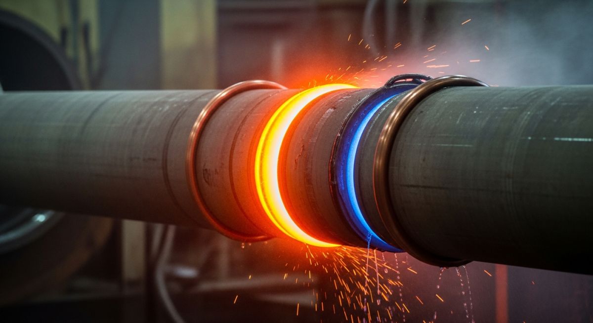
The mechanics of induction bending rely on localized, high-frequency electromagnetic induction. A copper induction coil surrounds a narrow section of the pipe, heating a circumferential band (typically 25mm to 50mm wide) to temperatures between 850°C and 1050°C for carbon steel. A hydraulic ram pushes the pipe forward at a highly controlled speed, while a mechanical pivot arm applies a bending moment to achieve the desired radius. Immediately after passing through the heating coil, the pipe is quenched with water or forced air.
This localized heating minimizes the force required to deform the metal, allowing us to bend large-diameter, heavy-wall pipes that would otherwise collapse under cold bending forces. Because the heated zone is so narrow, the surrounding cold material supports the pipe structure, keeping ovality and wall thinning to a minimum.
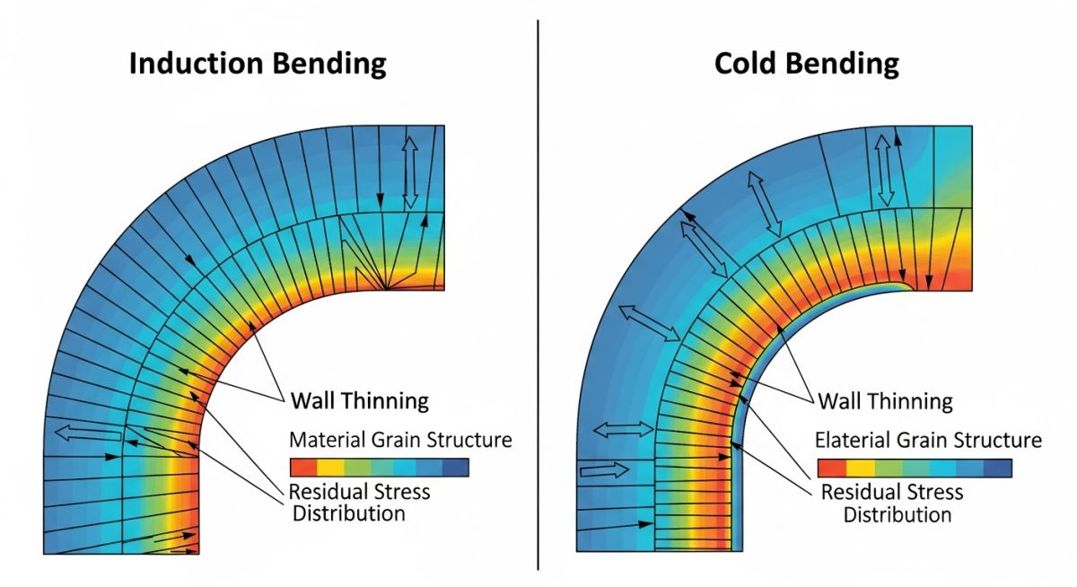
Wall Thinning and Ovality Calculations
When a pipe is bent, the outer radius (extrados) stretches and thins, while the inner radius (intrados) compresses and thickens. To ensure compliance with ASME B31.3 and ASME B16.49, we must calculate the minimum wall thickness at the extrados using the following engineering formula:
Where:
t_extrados = Minimum required thickness at the extrados after bending
t_min = Minimum calculated straight pipe thickness per ASME B31.3 Section 304.1.2
R = Bend radius of the pipe (mm)
r = Nominal outside radius of the pipe (mm)
For example, if you are bending a 12-inch Schedule 80 pipe (OD = 323.8 mm, r = 161.9 mm) to a 3D bend radius (R = 914.4 mm), the thinning factor is approximately 0.89. This means the extrados wall thickness will thin by roughly 11%. If your design pressure requires a minimum straight wall thickness of 10.3 mm, your starting mother pipe must have a nominal thickness of at least 11.6 mm to compensate for this thinning.
Ovality is another critical parameter that must be monitored. It is calculated as:
ASME B16.49 limits ovality to a maximum of 3% for high-pressure gas pipelines, and up to 5% for standard process piping systems. Excessive ovality introduces severe stress concentrations under cyclic pressure loading, which can lead to fatigue failure.
In my field audits, I have often found that fabricators skip the Post-Bend Heat Treatment (PBHT) on high-strength low-alloy (HSLA) steels like API 5L X70. Without proper tempering after the water quench, the heat-affected zone (HAZ) develops localized hard spots exceeding 300 HV. In sour service environments, these hard spots are highly susceptible to Hydrogen-Induced Cracking (HIC) and Sulfide Stress Cracking (SSC). Always mandate a hardness survey across the transition zone.
How Does Induction Bending Compare to Others?
To select the correct fabrication method, you must understand the operational limits of each process. Below is a comprehensive engineering comparison table that I use during the FEED (Front-End Engineering Design) phase of major projects.
| Parameter | Induction Bending | Hot Slab Bending | Cold Bending |
|---|---|---|---|
| Heating Method | Localized High-Frequency Induction | Furnace Heating (Entire Pipe) | None (Ambient Temperature) |
| Bend Radius Range | 1.5D to 10D+ (Highly Flexible) | 3D to 5D | 5D to 40D (Requires large footprint) |
| Wall Thinning (%) | 8% to 15% (Controlled) | 15% to 25% (High risk) | 10% to 18% (Radius dependent) |
| Ovality Control | Excellent (Typically < 3%) | Poor (Requires internal sand packing) | Moderate (Risk of buckling) |
| Microstructural Impact | Localized HAZ; requires PBHT | Full grain growth; requires normalizing | Work hardening; increases hardness |
| Governing Standards | ASME B16.49 / ISO 15590-1 | ASME B31.3 / PFI ES-24 | ASME B31.3 / PFI ES-24 |
This matrix maps the core technical entities, structural acronyms, and physical parameters to their governing international standards.
| Entity / Acronym | Technical Definition | Physical Parameter / Limit | Governing Standard |
|---|---|---|---|
| PBHT | Post-Bend Heat Treatment | Stress relieving or normalizing temp | ASME B31.3 Section 331 |
| HAZ | Heat Affected Zone | Hardness limit ≤ 248 HV (Sour Service) | NACE MR0175 / ISO 15156 |
| MPS | Manufacturing Procedure Specification | Mandatory qualification document | ISO 15590-1 |
| Extrados | Outer curve of the bend | Subject to wall thinning limits | ASME B16.49 |
| Intrados | Inner curve of the bend | Subject to wrinkling and thickening | ASME B16.49 |
How to Inspect Induction Bending Quality?
Before accepting any induction-bent components from a fabricator, your quality control team must execute a rigorous inspection protocol. Below is the exact checklist I use during shop inspections to prevent field fit-up issues and premature failures.
-
Verify MPS Approval: Ensure the Manufacturing Procedure Specification (MPS) is fully qualified per ISO 15590-1, including mechanical testing of a prototype bend.
-
Dimensional Inspection: Measure and record the bend angle, bend radius, ovality, and wall thickness at the extrados using calibrated ultrasonic thickness (UT) gauges.
-
Hardness Testing: Perform portable hardness testing across the transition zone, HAZ, and parent metal. Ensure hardness does not exceed 248 HV for sour service or 300 HV for standard service.
-
Non-Destructive Testing (NDT): Conduct Magnetic Particle Inspection (MPI) or Liquid Penetrant Inspection (LPI) on the entire outer surface of the bend to check for surface micro-cracks.
-
Review PBHT Charts: Verify that the time-temperature charts for post-bend heat treatment match the qualified procedure exactly.
Field Case Study: Real-World Application
During a major high-pressure gas transmission pipeline project (24-inch OD, API 5L X70, 14.3mm WT), the routing required several tight 3D bends to bypass an environmental reserve. The contractor proposed cold field bending. However, initial trial bends resulted in unacceptable ovality (up to 6.2%) and severe springback, which made field alignment impossible. Traditional hot slab bending was also ruled out because the prolonged furnace heating would destroy the micro-alloyed properties of the X70 steel, dropping its yield strength below the design minimum.
I stepped in and mandated the use of induction bending. We qualified a Manufacturing Procedure Specification (MPS) using a localized heating temperature of 950°C, a push speed of 15 mm/min, and immediate water quenching. This was followed by a full-body tempering heat treatment at 610°C for 1 hour. The results were outstanding: wall thinning was kept under 7.5%, ovality was reduced to a maximum of 1.8%, and the mechanical testing confirmed that the X70 yield strength and Charpy V-notch impact toughness were fully preserved.
This case study proves that for high-strength steels, induction bending combined with precise post-bend heat treatment is the only reliable method to achieve tight-radius bends without sacrificing material integrity.
Frequently Asked Engineering Questions
What is the minimum bend radius achievable with induction bending?
Is post-bend heat treatment (PBHT) always mandatory for induction bends?
How does cold bending compare to induction bending in terms of cost?
Can stainless steel pipes be induction bent?
What is the difference between induction bending and hot slab bending?
How do you prevent wrinkling on the intrados during induction bending?
===

